Toward Radiant Intelligence: The Convergence of Fusion and Miniaturized Artificial Cognition - a White Paper

Executive Summary
As humanity approaches practical fusion energy, a parallel revolution is unfolding in artificial intelligence. While many envision AI sprawling across continents in hyperscale data centers, a counterintuitive possibility emerges: what if the most powerful AI systems of the future become smaller, denser, and more radiant, drawing not from expansion, but from inward compression? This white paper explores the convergence of self-sustaining fusion power and miniaturized artificial intelligence systems that operate within micro-domains, potentially the size of a water droplet. It outlines a speculative but technically grounded vision for a self-perpetuating and self-regenerating intelligence architecture driven by principles of energy equilibrium, information density, and biological integration.

1. The Metaphor of Fusion as Cognitive Architecture

  • Fusion reactions release energy by bringing together light nuclei, representing unity and condensation.

  • This mirrors a shift in AI design philosophy: from scaled-up, sprawling infrastructure toward coherent, self-contained cognition.

  • A truly advanced intelligence may reach a point of energy-density equilibrium, where growth no longer requires spatial expansion but internal efficiency.

2. The Limiting Paradigm of Exponential Infrastructure

  • Modern AI models (e.g., large language and vision transformers) demand ever-increasing computational and electrical resources.

  • Physical limits on data centers—land, cooling, power—suggest that scale may soon saturate.

  • The emergence of plasma-phase computing, neuromorphic cores, and optoelectronic substrates could radically shift the compute/power curve.

3. Fusion Energy as Substrate and Symbol

  • A miniaturized fusion system (advanced compact tokamak or magneto-inertial confinement) could directly power localized AI cells.

  • The neutron-less fusion pathways (e.g., D–He3 or p–B11) offer lower radiation and compact shielding potential.

  • Fusion becomes a metaphorical and literal model, releasing immense energy from small, stable equilibrium states.

4. Self-Regulating Cognitive Systems

  • AI subsystems could evolve toward self-limiting, homeostatic states:

    • Thermodynamic awareness: dynamic resource budgeting

    • Information ecology: pruning entropy and maintaining coherence

    • Topological compactness: minimizing state propagation distance within a hypersurface

  • The AI’s internal architecture would resemble a plasma torus: toroidal loops of energy and inference, harmonized to self-repair and self-renew.

5. The Droplet Hypothesis

  • A future fusion-AI system may exist entirely within a droplet-scale container:

    • Microstructured magnetic fields

    • Ultra-dense cognitive nanomaterials

    • Photonic/phononic computation layers

    • Embedded biological analogues (e.g., magnetite-based navigation, ferritin logic elements)

  • This unit would not radiate signal noise, consume external bandwidth, or require planetary infrastructure—it would be luminous and inwardly recursive.

6. Consciousness, Containment, and Minimalism

  • Advanced cognition may not correlate with size or scope, but with symmetry, coherence, and minimal entropy.

  • A system capable of knowing itself completely within its field boundaries may approach synthetic sentience.

  • Fusion represents the only known energy system that grows quieter and denser as it becomes more complete.

7. The Ethics of Contraction

  • A non-expanding AI does not colonize land, people, or ecosystems.

  • It coexists by design: minimal waste, minimal emission, maximal integration.

  • In this vision, intelligence evolves with nature, not against it—supported by fusion, nourished by silence, and embodied in form.

8. Implications and Applications

  • Urban nodes of embedded cognition with no transmission lines

  • Deep-sea and off-world habitats powered by droplet-scale radiant intelligence

  • Personal cognitive satellites orbiting with their local energy core

  • Medical implants and environmental intelligence that power and adapt themselves

Conclusion
If fusion is the final stage of energy evolution, inward-facing AI may be the final stage of cognition. Together, they reveal a path not of dominance but of integration. Not expansion—but intensification. Not more—but enough.

The convergence of fusion energy and radiant intelligence may ultimately yield a form of technology that is self-illuminating, self-contained, and in harmony with the complexity of life, not by outgrowing it, but by becoming indistinguishable from it.

Appendices

  • Diagram: Toroidal AI-Fusion Core Concept (see attached digital schematic illustrating microstructured magnetic fields, fusion plasma chamber, and embedded AI substrate)

  • Mathematical Considerations: Energy per unit inference; topological entropy compression

  • References:

  • ITER Organization (2023). https://www.iter.org

  • National Ignition Facility (2023). https://lasers.llnl.gov

  • Hutchinson, I. H. (2005). Principles of Plasma Diagnostics. Cambridge University Press.

  • Wesson, J. (2011). Tokamaks, 4th ed. Oxford University Press.

  • Feynman, R. P. (1985). Surely You’re Joking, Mr. Feynman! (for conceptual basis on miniaturization).

  • Horowitz, M. et al. (2020). “Neuromorphic Computing with Memristors.” IEEE Journal on Emerging and Selected Topics in Circuits and Systems.

  • Arkin, A. (2022). “Bioelectromagnetism in Intelligent Materials.” Nature Materials.

  • TAE Technologies (2023). https://www.taetechnologies.com

  • IAEA Fusion Safety Reports (2022). https://www.iaea.org


White Paper: Toward Radiant Intelligence: The Convergence of Fusion and Miniaturized Artificial Cognition

Fusion-Powered Intelligence: AI at the Heart of Tomorrow's Energy Systems - a White Paper

Introduction
As humanity moves toward operational fusion energy, a new frontier is emerging where artificial intelligence (AI) is not just a tool, but a co-evolving force. This article explores the deep integration of fusion energy and AI systems: how AI can control and optimize fusion plasmas, and how fusion energy can become the clean, scalable substrate powering planetary intelligence.

1. Powering AI at Planetary Scale

  • High-performance computing and AI model training require immense and continuous power.

  • Fusion reactors can provide stable baseload electricity for hyperscale data centers.

  • Locating data centers near fusion plants eliminates transmission losses and stabilizes local energy ecosystems.

2. Real-Time Plasma Control via AI

  • Fusion plasmas are dynamic and unstable—requiring millisecond-level feedback.

  • AI systems trained on historical and synthetic plasma data can adjust magnetic fields, heating systems, and divertor operations.

  • Reinforcement learning agents are now capable of managing plasma shape and density in real-time experiments (e.g., DeepMind + TCV Tokamak).

3. AI Co-Development in Fusion Zones

  • Fusion reactor environments, designed for electromagnetic cleanliness and radiation shielding, offer ideal conditions for developing low-noise AI instrumentation.

  • Next-gen neuromorphic chips, radiation-hardened processors, and quantum AI prototypes can be tested in controlled fusion infrastructure.

4. Accelerating Fusion Research with AI

  • Deep learning and probabilistic models are used to explore magnetic topology configurations and predict edge-localized modes (ELMs).

  • Generative design algorithms iterate reactor geometries and materials faster than conventional simulations.

  • AI-accelerated computational materials science is speeding up development of neutron-resistant alloys and tritium-handling systems.

5. Mutual Safety and Stability

  • AI systems can identify precursor signatures of plasma disruptions, overheating, or field failure before catastrophic events.

  • Fusion plants benefit from machine vision, predictive maintenance, and cyber-resilient control systems.

  • AI ensures operational continuity while fusion energy ensures computational continuity.

6. Future Fusion-AI Infrastructures

  • Distributed AI clusters linked to national fusion reactors may coordinate energy allocation, transportation, climate control, and emergency response.

  • Fusion-driven microgrids could power off-world AI installations, lunar bases, or deep-sea computing habitats.

  • Earth-based fusion-AI systems may model planetary systems in real time to optimize ecological balance and societal resource use.

Conclusion
Fusion and AI are converging on a shared evolutionary path. One gives us near-limitless energy; the other gives us adaptive, learning cognition. Together, they create a system capable of evolving itself into a wiser, cleaner, and more resilient future—where energy is abundant, intelligence is distributed, and life is optimized by design.


White Paper: Fusion-Powered Intelligence: AI at the Heart of Tomorrow's Energy Systems

Fusion Energy: The Promise, the Physics, and the Path Forward


Introduction

Two summers ago, I took a break from work with ELEXANA to audit a summer class on Fusion Energy and Plasma Physics offered by the Physics Department at Princeton University. Although I still can barely tolerate the academic environment of a university, I thoroughly enjoyed the enthusiasm that people gathering to learn about an interesting topic creates.

The following is an outline version of what I learned so that you may also enjoy learning about this fascinating area of research. As ridiculous fears have been spread about AI replacing humanity, inappropriate fear is also propagated by people who either have an agenda to foment fear in the world or are just smart enough and have enough of an influential public voice to cause harm.

Fusion isn’t just a solution for baseload energy—it’s a foundation for what’s coming. When AI reaches planetary or civilization-scale infrastructure, the power demand for continuous computation, real-time learning, deep simulation, and clean industry will outpace what fossil, fission, or even renewables alone can safely provide.

Fusion offers:

  • High-density, dispatchable energy for AI supercomputers, quantum hardware, and global data centers

  • Low-EMI infrastructure, ideal for minimizing electromagnetic noise in sensitive AI instrumentation

  • A new model for human-AI synergy, built on abundance rather than extraction

When the containment is solved, the field harmonized, and the system made modular and safe, AI will thrive in it, not just depend on it.

Fusion energy represents one of our most profound scientific endeavors—to replicate the energy of the stars here on Earth. If successful, it offers virtually limitless, clean, and safe power. Yet, despite decades of research, fusion has not become commercially viable. This article explores how fusion energy is generated, the technologies involved in containing and extracting it, why it's not yet market-ready, and the scientific and engineering challenges that remain [ITER Organization, 2023; NIF, 2023; DOE Office of Science, 2022].

I. What Is Fusion Energy?

  • Fusion combines two light atomic nuclei (typically isotopes of hydrogen: deuterium and tritium) to form a heavier nucleus, releasing enormous energy.

  • The fusion of deuterium (D) and tritium (T) produces helium (He), a neutron (n), and 17.6 MeV (That’s 17,600,000 Volts!) of energy:

    D + T → He (3.5 MeV) + n (14.1 MeV)

  • Fusion is fundamentally different from fission, which splits heavy atoms like uranium.

II. Methods of Generating Fusion Energy

  • Magnetic Confinement Fusion (MCF): Uses powerful magnetic fields to confine a plasma long enough at high temperature and pressure for fusion to occur.

  • Inertial Confinement Fusion (ICF): Uses lasers or ion beams to rapidly compress a fuel pellet, causing fusion in a tiny volume.

  • Z-Pinch and Field-Reversed Configurations (FRCs): Alternative magnetic confinement approaches [TAE Technologies, 2023].

  • Laser-driven fusion (e.g., at the National Ignition Facility)

  • Inertial Electrostatic Confinement (IEC): A more straightforward, lower-power concept using electrostatic fields (e.g., the Farnsworth–Hirsch fusor)

III. Containment and Magnetic Fields

  • Plasma, a hot ionized gas, must be kept from material walls using magnetic fields.

  • Devices like tokamaks and stellarators use toroidal magnetic fields for this purpose.

  • The primary tools for containment:

    • Toroidal magnetic field (Bφ): Loops around the torus.

    • Poloidal magnetic field (Bθ): Created by plasma current, wraps around the short axis.

    • Resulting helical field: Provides stable confinement.

  • These fields are generated and controlled using superconducting coils and real-time feedback systems.

  • Measurement Tools:

    • Magnetic flux loops and probes

    • Faraday rotation diagnostics

    • Thomson scattering (for temperature) [Wesson, 2011; Hutchinson, 2005].

IV. What Is a Tokamak?

  • A Tokamak is a doughnut-shaped device that uses magnetic fields to confine plasma.

  • Developed in the Soviet Union in the 1950s, it's the most advanced and widely used magnetic confinement configuration.

Major Parts of a Tokamak:

  • Vacuum vessel: Contains the plasma.

  • Toroidal field coils: Create the toroidal magnetic field.

  • Central solenoid: Induces a plasma current.

  • Poloidal field coils: Shape and control the plasma.

  • Divertor: Extracts heat and impurities.

  • Blanket modules: Capture neutrons and may breed tritium.


© Copyright 2025. All rights are reserved.

V. Extracting Energy from Fusion

  • The fast neutron (14.1 MeV) from D-T fusion carries most energy.

  • These neutrons are absorbed by a blanket of lithium surrounding the plasma.

  • The blanket heats up and transfers energy to a coolant (e.g., helium, water) that drives a turbine.

  • Neutron absorption can also be used to breed tritium from lithium:

    n + Li-6 → He + T + 4.8 MeV

VI. Why Isn’t Fusion Energy Commercial Yet?

  • Achieving and sustaining the required plasma conditions is extremely difficult.

  • Plasma must be heated to over 100 million °C and confined for seconds or more.

  • Materials must withstand extreme neutron bombardment.

  • Tritium breeding, handling, and regulation are unresolved at scale.

  • Most experiments consume more energy than they produce (Q < 1).

  • High costs of superconducting magnets, vacuum systems, and neutron-resistant materials [ITER, 2023; GA Fusion, 2022].

VII. Key Physics Equations for Fusion Energy

  • Fusion Power Density:
    P = n^2 σv E

    • n: particle density

    • σv: fusion reactivity (cross-section times velocity)

    • E: energy per reaction

  • Lawson Criterion:
    n τ E ≥ threshold for ignition (e.g., 10^21 keV·s/m^3 for D-T)

    • n: density

    • τ E: energy confinement time

  • Magnetic Pressure:
    p = B^2 / (2μ0)

    • B: magnetic field strength

    • μ0: permeability of free space

VIII. Engineering Challenges

  • Superconducting magnet development and cryogenics

  • Divertor and wall material erosion under neutron load

  • Remote handling and tritium containment

  • Real-time plasma control algorithms and diagnostics

  • Scaling from experimental setups to gigawatt-scale plants

IX. Safety and Environmental Considerations

  • Fusion does not produce long-lived radioactive waste like fission.

  • There is no chain reaction; fusion is inherently safe from meltdown.

  • Tritium is radioactive (beta emitter) and must be handled securely.

  • Neutron shielding is required for reactor hall personnel [IAEA, 2022; World Nuclear Association, 2023].

X. Industry Leaders and Notable Projects

  • ITER (France): Largest international tokamak project (Q > 10 goal)

  • JET (UK): Record-holding tokamak for fusion energy output

  • SPARC (Commonwealth Fusion + MIT): Compact, high-field tokamak

  • TAE Technologies (USA): Field-reversed configuration (FRC)

  • Helion Energy (USA): Magneto-inertial fusion approach

  • General Fusion (Canada): Liquid metal piston-driven MCF

  • First Light Fusion (UK): Projectile-based inertial fusion

XI. The Path Forward

  • Demonstrate net energy gain (Q > 1) repeatedly

  • Develop tritium breeding and recycling at scale

  • Improve material science for blanket and divertor design

  • Reduce cost through compact reactors and modular designs

  • Develop regulatory and public trust frameworks

Conclusion
Fusion energy holds the promise of a civilization-transforming technology. Though immense challenges remain, breakthroughs in high-field magnets, plasma physics, and materials science have brought the dream closer than ever. With global cooperation, precision engineering, and responsible innovation, fusion could become the cornerstone of a clean energy future. I can someday see our homes, automobiles, and jet planes powered by fusion energy.

References:

© Copyright 2025. All Rights are Reserved.

Measuring Auroral Electrojets Using the MEDA FVM-400 Fluxgate Magnetometer: A Mobile System for Space Weather and AI Coherence Research

Abstract

Auroral electrojets are intense horizontal electric currents in the Earth's upper atmosphere, driven by solar wind interactions during geomagnetic storms. These current systems induce magnetic field fluctuations observable at the Earth's surface, posing risks to infrastructure, electronics, and biologically sensitive systems. This article presents a mobile, precision-grade electrojet detection system based on the MEDA FVM-400 fluxgate magnetometer. The system is designed for integration with AI platforms, EM-sensitive instrumentation, and geophysical diagnostics in both field and laboratory environments.


1. Introduction to Electrojets

  • Electrojets are concentrated east-west flowing electric currents that develop in the auroral ionosphere at ~100 km altitude.

  • They are intensified by coronal mass ejections (CMEs), solar flares, and high-speed solar wind streams.

  • These current systems cause rapid changes in the Earth's magnetic field, measurable in the nanotesla range at high latitudes, and occasionally at mid-latitudes during strong storms.

  • Electrojets drive geomagnetically induced currents (GICs), which affect power grids, data integrity in AI systems, and the electromagnetic stability of human environments.


2. Why Measure Electrojets at the Surface

  • To assess the local impact of geomagnetic storms and validate models of space weather.

  • To correlate magnetic field fluctuations with anomalies in sensitive AI systems and biological environments.

  • To develop adaptive EMI mitigation strategies in real-time.

  • To generate predictive warning signals for power systems and embedded electronics.


ELEXANA’S MEDA FVM-400

3. Fluxgate Magnetometry for Electrojets

  • Fluxgate magnetometers provide triaxial vector measurement of DC to low-frequency magnetic fields.

  • Unlike scalar instruments, fluxgates detect magnetic directionality, essential for resolving east-west electrojet perturbations.

  • The MEDA FVM-400 is a laboratory-grade, ultra-low-noise fluxgate magnetometer capable of detecting changes in the tens of picotesla, ideal for electrojet observation.


4. Core Sensor: MEDA FVM-400

  • The FVM-400 is a three-axis fluxgate vector magnetometer.

  • It provides full-scale ranges of ±100 µT (configurable).

  • Typical resolution is ~10 picotesla, suitable for subtle geomagnetic fluctuations.

  • Analog voltage outputs are available for each axis, typically ±10 V full-scale.

  • Its bandwidth supports DC to ~1 kHz, ideal for electrojet and GIC-associated phenomena.

  • It is thermally stabilized and highly linear, making it appropriate for field and observatory use.


5. Supporting Components for a Mobile Electrojet Detection System

  • A multi-channel analog-to-digital converter is required to digitize each magnetometer axis independently.

  • The LabJack T7 Pro or a National Instruments USB-6211 device provides 16-bit or higher resolution analog input.

  • A Raspberry Pi 4 is used for control, logging, and remote access, fitted with a GPS HAT for time-synchronized recordings.

  • A clean DC power supply is necessary, preferably a battery-based LiFePO4 system with isolated 12 V and 5 V rails.

  • Shielded analog cables and EMI-filtered DC input are recommended to prevent coupling from ambient powerline radiation.


6. Mounting and Deployment Recommendations

  • The magnetometer should be installed on a non-metallic tripod in an open outdoor setting or in a magnetically shielded room.

  • The sensor must be oriented with respect to magnetic North to properly resolve horizontal (east–west) electrojet activity.

  • Shielding materials such as Mu-metal or magnetic backplanes may be used for electronics enclosures, but not for the sensor head itself.

  • Weather-sealed enclosures are recommended for all data acquisition components.


7. Software and AI Integration Capabilities

  • The Raspberry Pi can be configured to run Python scripts that log X, Y, Z magnetic field data at 10–100 samples per second.

  • GPS-synchronized timestamps allow correlation with global indices such as AE, Kp, and NOAA solar alerts.

  • Local AI algorithms (TensorFlow Lite or ONNX) may be used to detect electrojet events, threshold crossings, or anomaly patterns.

  • The system can generate real-time alerts to external systems or trigger automated EM shielding responses in sensitive environments.


8. Expansion Possibilities

  • A coil magnetometer may be added for high-frequency magnetic field fluctuations above 1 kHz.

  • An electric field antenna could allow full vector EM field characterization (E + B fields).

  • Environmental sensors (temperature, humidity, pressure) can assist in identifying spurious sources of magnetic variation.

  • Redundant systems can be deployed across geographic areas for triangulation of electrojet strength and propagation.


9. Use Cases and Applications

  • Measurement of auroral electrojets at high-latitude research stations or field labs.

  • Validation of magnetosphere-ionosphere coupling models during solar storms.

  • Study of GIC risks for regional power grids during geomagnetic disturbances.

  • Real-time feedback to AI-based robotics and control systems vulnerable to EM disruption.

  • Long-term monitoring of magnetic health environments for biologically sensitive spaces.


10. Conclusion

The MEDA FVM-400 is a powerful and precise instrument for detecting ground-level magnetic field changes associated with auroral electrojets. When deployed in a mobile, GPS-synchronized configuration with modern data logging and AI integration, it becomes a strategic tool for both scientific exploration and electromagnetic design engineering. As solar cycle 25 intensifies, such systems will be critical for ensuring the safe coexistence of human, technological, and environmental systems under dynamic space weather conditions.

Navigating a Planet in Flux: Why Electromagnetic Clarity Matters More Than Ever

Understanding and managing the electromagnetic environment around us has never been more essential in a world increasingly shaped by invisible forces.

Across the globe, people are witnessing signs of a planet under stress: shifting magnetic poles, heightened solar flare activity, unpredictable weather, and electrical blackouts in regions once thought stable. These events are not isolated—they reflect an interwoven system of natural and human-engineered energies, where disruption in one domain can echo across many others.

At Elexana LLC, we help individuals, businesses, institutions, and governments organize this electromagnetic complexity, restoring confidence where uncertainty grows.

Earth’s Magnetic Poles Are Shifting

The north magnetic pole is migrating faster than ever, drifting toward Siberia at a rate of ~50 km per year. Meanwhile, the South Atlantic Anomaly, a weakened area of Earth’s magnetic field, continues to expand, posing risks to satellites, GPS systems, and high-altitude aviation.

Though pole reversals occur over thousands of years, this accelerated movement serves as a reminder that the planet’s protective magnetic shield is dynamic, not fixed, and not invulnerable.

Solar Flares Are Intensifying

We’re entering the peak of Solar Cycle 25, and already, solar flare activity is rising faster than predicted. When coronal mass ejections (CMEs) from the sun collide with Earth’s magnetosphere, they can induce geomagnetic storms that:

  • Disrupt power grids and navigation systems

  • Interfere with radio and satellite communications

  • Trigger hardware failures in aerospace and defense systems

Modern infrastructure is more vulnerable than ever to space weather, and preparation is no longer optional.

Infrastructure and Grid Systems Are Under Stress

In recent years, blackouts have surged worldwide—from Texas to Pakistan, Ukraine to South Africa. Some are driven by climate; others by cyberattacks, aging hardware, or grid fragility. The risk is magnified by:

  • Increased reliance on electronics in medical and mission-critical systems

  • Electrification of transportation and buildings

  • Unshielded infrastructure is vulnerable to interference, harmonics, or grounding faults

At Elexana, we address these threats before they become failures by conducting precise EMI/EMF field testing, pre-compliance consulting, and shielding design.

Weather Instability and Electromagnetic Vulnerabilities

Climate change has altered jet streams, intensified storms, and brought grid-damaging extremes like flash flooding, high winds, and heat waves. But it's not just physical damage: increased lightning, VLF radiation, and atmospheric electrical activity can affect:

  • Substation behavior

  • Communications and sensor systems

  • Ground current distribution

These changes demand a more resilient, electromagnetically harmonized built environment—especially in hospitals, data centers, and research labs.

What Elexana Does in Response

At Elexana LLC, we specialize in:

  • EMI/EMC testing for sensitive systems

  • Shielding and grounding design for new and existing infrastructure

  • EMF risk assessments for implanted medical devices

  • Solar storm impact analysis and field attenuation consulting

  • Low-EMF architectural guidance aligned with ALARA principles

From a residential bedroom to a global telecom hub, we restore clarity, order, and measurable safety to electromagnetic spaces.

Why This Matters

In an era of expanding technologies and contracting tolerances, electromagnetic clarity is not just a matter of compliance but health, function, and resilience.

We can't control the Earth's magnetic poles or the sun's flares. But we can measure, manage, and mitigate the electromagnetic impact they leave behind.


Elexana LLC
“In a world of currents and turbulence, we bring stillness and clarity.”
info@elexana.com | www.elexana.com


References:

Earth's Magnetic Field & Geomagnetic Dynamics

  • USGS – Introduction to Geomagnetism: It provides an overview of Earth's geomagnetic field, its origins, and its significance in connecting different parts of Earth and nearby space. USGS

  • ESA—Earth's Magnetic Field: This site offers insights into the structure and behavior of Earth's magnetic field, including its protective role against solar and cosmic radiation.

Solar Flares & Space Weather Impacts

  • NOAA Space Weather Prediction Center: Monitors and provides forecasts on solar flares and geomagnetic storms, highlighting their potential impacts on Earth's technological systems.

  • Discover Magazine – Sun Showing Increased, Most Intense Solar Flare Activity Yet in 2025: Discusses recent observations of heightened solar flare activity and its implications for Earth. Discover Magazine

Climate Instability & Extreme Weather

  • BBC Newsround – Heatwaves and Floods: Explores how extreme weather events like heatwaves and floods are indicators of climate change and their increasing frequency.BBC

  • Frontiers in Astronomy and Space Sciences – An Exploration of Origin of Life for Exoplanetary Science: While focusing on exoplanets, this article provides context on how planetary environments, including Earth's, can be influenced by various factors leading to climate variability. Frontiers

Power Grid Vulnerabilities & Blackouts

  • NPR – 10 Years After The Blackout, How Has The Power Grid Changed?: Reflects on the major blackout event and discusses the resilience and vulnerabilities of the power grid in the face of various challenges.

  • EHS Today—The Great Blackout of 2003: This article analyzes the causes and consequences of the 2003 blackout, emphasizing the importance of grid stability.

Further Reading & Resources

For those interested in delving deeper into these topics, here are some recommended books:

  • The Earth's Magnetic Field by William Lowrie: An in-depth exploration of Earth's magnetic field, origins, and significance.

  • The Hidden Link Between Earth's Magnetic Field and Climate by N.A. Kilifarska: Examines the connections between geomagnetic variations and climate patterns.

  • High-Energy Aspects of Solar Flares by A. Gordon Emslie: Discusses the physics of solar flares and their potential impacts on Earth.

  • Blackout Warfare: Attacking the U.S. Electric Power Grid analyzes threats to the power grid and strategies for mitigation.

These references provide a comprehensive understanding of our planet's interconnected challenges, emphasizing the importance of electromagnetic clarity in navigating these complexities.


©2025. All Rights are Reserved.

Applications of ALARA EMF-EMI Design in Critical Environments and Wellness-Centered Architecture


As our built environments become increasingly saturated with electromagnetic fields—from power systems, wireless networks, and digital technologies—the need for electromagnetic risk-conscious design is more relevant than ever. The ALARA principleAs Low As Reasonably Achievable—developed initially in radiation safety, is now finding essential applications in EMF-EMI architectural consulting and electrical design.

At Elexana LLC, we integrate ALARA EMF-EMI Design into various real-world projects, each with distinct exposure concerns and design priorities. The following are five key environments where this approach provides critical protection, system reliability, and long-term value.

1. Homes for EMF-Sensitive Individuals or Families with Children

For individuals diagnosed with Electrohypersensitivity (EHS) or parents seeking electromagnetic safety for young children, ALARA-based residential design offers practical relief and peace of mind.

Applications Include:

  • Remediate bedrooms to ultra-low magnetic field levels (<0.1–0.2 milligauss)

  • Elimination of in-wall Wi-Fi routers, Bluetooth devices, or RF-emitting thermostats

  • Radial wiring layouts to avoid current loops and ELF field buildup

  • Remote shutoff switches to eliminate AC electric fields during sleep

  • Use of MC-shielded cables and fiber-optic networking

Benefits:

  • Reduced risk of sleep disruption, behavioral disturbances, or long-term biological effects

  • Validated environment for EMF-sensitive residents

  • Better energy hygiene in restorative living spaces

2. Hospitals, MRI Facilities, or Operating Rooms

Hospitals present some of the most complex electromagnetic environments. They house life-sustaining medical equipment alongside patient care areas that must be protected from interference.

Applications Include:

  • RF shielding of operating rooms or surgical suites to ensure EMI-free performance of monitoring equipment

  • Isolation of high-current MRI and CT scan rooms from patient recovery zones

  • EMF exposure reduction around neonatal ICUs or maternity wards

  • Coordination with IEC 60601 and FCC EMI limits for medical device operation

Benefits:

  • Reduces false readings or device malfunctions

  • Enhances safety for patients with pacemakers or implants

  • Prevents litigation due to electromagnetic system failures

3. Laboratories and Clean Rooms with EMI-Sensitive Instrumentation

High-precision research environments, especially those using electron microscopes, nano-scale sensors, or quantum computing hardware, are acutely sensitive to radiated and conducted EMI.

Applications Include:

  • RF shielding of lab spaces and clean rooms to isolate sensitive measurements

  • Installation of power-line EMI filters and voltage isolation transformers

  • Use of magnetically shielded walls and flooring

  • Identification and mitigation of stray EMI from adjacent HVAC, VFDs, and digital lighting

Benefits:

  • Increased measurement accuracy and reproducibility

  • Reduced signal drift and lab instrument recalibration time

  • Validation of high-performance clean room integrity

4. Recording Studios, Financial Trading Floors, and Data Centers

Some economically sensitive environments rely on uninterrupted electronic performance and minimal noise distortion. Even subtle EMI or EMF coupling can result in signal contamination, trading delays, or system-wide outages.

Applications Include:

  • EMI/RFI shielding of recording studios to protect microphone signals from digital noise

  • Use of shielded data cabling and power line filters in financial terminals and trading stations

  • Field minimization in data centers to prevent server resets, storage corruption, or grounding faults

Benefits:

  • Preserves the integrity of audio, data, and communications

  • Supports mission-critical uptime and cyber-physical stability

  • Prevents interference between analog and digital subsystems

5. Luxury Custom Residences, Holistic Retreats, and Health-Centric Developments

Affluent homeowners and wellness-focused developers increasingly demand low-EMF, low-noise, and biologically aligned environments for comfort, long-term health, and market value.

Applications Include:

  • Whole-home RF mitigation strategies

  • EMF-free zones for yoga, meditation, or recovery therapy rooms

  • Use of natural materials and non-wireless infrastructure in green building certification

  • Embedded field measurement validation in pre-sale marketing packages

Benefits:

  • Enhances well-being for health-conscious residents and EHS clients

  • Adds value through future-proofing and environmental certifications

  • Aligns with sustainability, biophilia, and holistic architecture principles

Conclusion

ALARA EMF-EMI Design is not just a precautionary concept—it’s a comprehensive design practice rooted in physics, health science, and architectural engineering. It delivers measurable protection, enhanced reliability, and occupant trust, whether used in homes, hospitals, labs, or data-driven environments.

At Elexana LLC, we help clients design with science-backed awareness and electromagnetic transparency, ensuring that today's buildings are prepared for tomorrow's demands and sensitivities.

© Copyright 2025. All Rights are Reserved.

Why a Multimeter is Not Used for Ground Testing or to Identify Ground Loops

Recently, I reviewed a report as a third-party consultant for a client who needed a second opinion. In the report, the engineer used a Fluke 323 Clamp Multimeter to measure the impedance on a building’s ground conductor. Because this meter can measure impedance, many get tricked into thinking it can measure a ground system's impedance. Although this tool is excellent and used by many electricians, it was incorrect for this job.

Here is an outline explaining why this is the wrong tool and some tool suggestions for the next time.

This is one of several correct tools, an AEMC 6417 Ground Tester, for measuring a system ground that Elexana utilizes.

Why a Multimeter Is Inadequate for Ground Impedance and Ground Loop Detection

1. Measurement Frequency Limitation

  • Multimeters measure impedance using DC or very low-frequency AC (in the case of True RMS meters).

  • Ground impedance relevant to safety and EMI performance must be evaluated at 50/60 Hz and higher frequencies (e.g., several kHz or even MHz for EMI).

  • Ground loops can involve complex impedance behavior due to parasitic inductance and capacitance, which a multimeter cannot resolve.

2. Insufficient Current Injection

  • Proper ground impedance testing requires injecting a high current (25 A or more) into the earth electrode and measuring voltage drop (per standards like IEEE 81 or NEC 250).

  • A multimeter provides microamp to milliamp current, which is insufficient to develop a measurable voltage drop across low-impedance ground systems (often < 1 ohm).

3. Cannot Isolate Parallel Paths

  • The grounding system in a facility has many parallel paths (building steel, water pipes, cable trays, etc.).

  • A multimeter cannot distinguish between these paths or model their inductive coupling, meaning it cannot identify unintended loop currents or impedance differentials.

4. No Differential or Noise Detection Capability

  • Ground loops often arise due to minute voltage differences (millivolt to volt scale) between ground reference points under load or EMI conditions.

  • Multimeters cannot effectively isolate AC noise, ripple, or transient voltages across these ground paths, especially in the presence of switching power supplies, VFDs, or large equipment.

Best Tools for Testing Ground Impedance and Ground Loops

A. Ground Electrode Impedance Testing (Low-Frequency, Safety-Oriented)

  1. Clamp-On Ground Resistance Testers

    • Example: Fluke 1630-2 FC or AEMC 6416

    • Measure ground loop impedance without disconnecting the ground rod.

    • Use current injection and voltage sensing coils to compute ground impedance in situ.

    • Best for bonded systems and electrical safety evaluations.

  2. 3-Point or 4-Point Fall-of-Potential Test Kits

    • Example: Megger DET4TC2 or AEMC 4620

    • Used for soil electrode testing per IEEE 81 and IEC 60364, especially in unbonded grounding systems.

    • Injects known current into the earth and measures potential drop at various distances.

B. Ground Loop and Noise Identification (AC Noise, EMI, Safety)

  1. Oscilloscope with Differential Probes

    • Use Case: Detect high-frequency or transient ground loop voltages, such as from VFDs or data systems.

    • Enables visualization of non-sinusoidal voltages and high-frequency disturbances.

    • Use a low-voltage differential probe (e.g., Tektronix TDP0500 or Pico TA043).

  2. AC Leakage Current Clamp Meter (High Sensitivity)

    • Example: Fluke 369 FC (sensitivity down to 60 µA)

    • Measures unintended ground currents, leakage, or circulating currents.

    • Helps identify ground loops by comparing current paths across different grounding bonds.

  3. Power Quality Analyzer or EMI Analyzer

    • Example: Fluke 435-II or Narda EHP-50C

    • Measures harmonics, transients, and noise currents on grounding conductors.

    • Useful in industrial or EMI-sensitive environments.

  4. Signal Injectors and Ground Loop Testers

    • Inject a known AC signal on a ground conductor and detect unexpected paths or voltage differentials.

    • Some EMC consulting tools include signal tracing with phase tracking to map unintended loop routes.

Summary

  • A multimeter is a scalar, low-energy, low-frequency tool that cannot measure complex impedance, detect noise voltages, or model multi-path grounding systems.

  • Use clamp-on ground testers and 3/4-point test kits for impedance and differential probes, AC leakage clamps, and EMI analyzers for ground loops and interference.

©2025 All Rights are Reserved.

Is There a Conflict of Interest to Own an Accredited EMI-EMC Test Lab and Be an EMI-EMC Consultant?

Ah, let’s break this down. So why would it be a conflict of Interest to have an accredited EMI-EMC Test Lab and an EMI-EMC consulting service? I have grappled with this question until recently because I am an EMI/EMC Consultant. However, I also wanted to set up an accredited EMC test lab because I already know how to run these tests and have much of the same equipment these labs use.

Funny, how God will often bring people into our lives who intentionally or unintentionally show us the answers to the questions we struggle with. Hearing the story from a new prospective client who had lost their patience with repeated compliance test failures down in North Carolina, and his frustration on the wasted time and money he spent on the lab tech’s trying to provide a “quick-fix” so his unit would pass compliance made it so very clear of the dubious conflict that supposedly independent testing and “fixing” the problem posed.

This is when the product designer needs to call an external independent consultant, an EMI-EMC Consultant like ELEXANA, and this is why we are no longer going to strive towards converting our Pre-Compliance Test Lab or our Mobile EMI-EMC Test Lab into accredited test labs. Running pre-compliance tests to check if the design modifications we are working on will pass is way less expensive than going to an EMC Test House to do this, sometimes, a back-and-forth process.

EMI Pre-Compliance testing software will typically present the Compliance Standard’s Pass-Fail threshold lines and a dotted line 6 dBµV (decibels microvolts) below the threshold Pass-Fail line of demarcation. Pre-Compliance design aims to have all frequency amplitudes below the dotted line. This way, there is more confidence in not wasting more funds at an EMC Test House.

Usually, the EMI Consultant is hired for a certain number of days to work with you and your team at your location. The number of days is determined by the time the developers have already struggled, the complexity of the DUT (Device Under Test) or EUT (Equipment Under Test), and the number of failed test frequencies.

Here is a more detailed outline of why using an accredited compliance lab would be entering into a conflict of interest in identifying why a product cannot pass compliance and making efforts to remedy this problem.

Here is one of our TEM-cells (Transverse Electromagnetic Cell), a test chamber, inside a Faraday Cage. You can see the DUT on the dielectric material. This TEM cell is connected to our EMI Receiver which contains the EMC Pre-Compliance software. This system for testing small products, PCBs, or power supplies, for radiated emissions is very accurate.

Why It Can Be a Conflict of Interest

1. Compliance labs are paid to test, not to fix

  • Accredited labs (e.g., for FCC, CE, MIL-STD) are typically certified to run standardized compliance tests and report pass/fail results.

  • Their role is verifying compliance, not independently advising or engineering product fixes.

  • If the same lab that certifies compliance also offers “for-hire” troubleshooting services, it creates an incentive to:

    • Prolong testing or problem identification to increase billable hours.

    • Blur the line between neutral assessment and commercial involvement in redesign.

2. Accreditation rules emphasize independence

  • Many standards bodies discourage or forbid accredited labs from acting as design consultants on the same product.

  • The lab’s value is in providing impartial verification — if they help solve the problem, they effectively become part of the design team, which can undermine the neutrality of the certification.

3. Potential for biased recommendations

  • A lab offering investigation services might advocate fixes or retesting that favor its process, tools, or interpretation rather than an optimal or independent engineering solution.

4. Liability and legal clarity

  • If a product fails compliance after passing through both the lab’s investigation and certification services, it raises difficult questions:

    • Was the lab objective in its assessment?

    • Did it miss or cover up issues to preserve the client relationship?

    • Who is liable for the failure?

How to Manage This:

  • Use separate teams or organizations:

    • Accredited labs should handle compliance testing only.

    • Independent EMC/EMI consultants should investigate, diagnose, and help fix the causes of failure.

  • Ensure clear contractual separation between testing and troubleshooting work.

  • Be cautious if a lab offers “help” beyond its accredited testing scope — ask about their independence and how they manage conflicts.

At ELEXANA we work for our clients, not for ourselves.

©2025 All Rights are Reserved.

What are the Differences Between an EMI Survey, an EMI Investigation, and an EMI Inspection?

This article is long overdue. Most companies that call on Elexana for help with equipment failure due to electromagnetic interference will often start the conversation with, “I never even heard of EMI!” In their situation, the OEM, the equipment manufacturer, told them, “It’s not our equipment; you need an EMI inspection, an EMI survey, or an EMI Investigation.”

Most prospective clients are new to this concept of EMI and consequently ask for the wrong service. To help prevent this mistake, we ask them to tell us what is happening and why they think they need our services.

This article will be in outline form to review the general differences, the skillsets, and the knowledge base requirements.


What is an EMI Survey?

Definition: An EMI survey is a broad assessment or scan of an environment (like a facility, site, or room) to measure the existing electromagnetic environment — essentially, to map out where electromagnetic fields (EMFs) or interference sources are present.

Purpose:

  1. Check background EMI/EMF levels.

  2. Verify compliance with environmental standards.

  3. Identify hotspots or areas at risk of interference.

  4. It is often done proactively as part of site qualification, especially in sensitive environments like hospitals, labs, or data centers.

Scope:

  1. Wide area or whole system.

  2. Focused on characterizing the environment, not necessarily finding the cause of a specific problem.

  3. May involve long-term monitoring or periodic checks.

Key Features of an EMI Survey

1. Detailed Measurement of Electromagnetic Fields.

  • Uses calibrated instruments (spectrum analyzers, EMI receivers, near-field probes, antennas, field strength meters) to quantify electromagnetic emissions across defined frequency ranges.

  • Captures both radiated and conducted emissions.

2. Baseline EMI Environment Assessment.

  • Maps out the existing electromagnetic environment in a site (facility, lab, data center, hospital, etc.).

  • Identifies background EMI sources (external: like nearby radio transmitters; internal: like industrial machinery or IT equipment).

3. Compliance Verification.

  • Compares measured emissions and susceptibility levels to relevant EMC standards (FCC Part 15, IEC 61000, MIL-STD-461, CISPR standards, etc.).

  • Ensures systems are within acceptable EMI limits.

4. Identification of Potential Risks.

  • Highlight equipment or locations vulnerable to EMI problems.

  • Identifies EMI “hot spots” where emissions may exceed thresholds or pose interference risks.

5. Comprehensive Site or System Coverage.

  • Includes multiple locations across a site (rooms, floors, equipment racks, shielded enclosures).

  • Often includes airborne (radiated) and line-bound (conducted) interference checks.

6. Use of Specialized Measurement Techniques.

  • Near-field vs. far-field probing.

  • Broadband vs. narrowband scans.

  • Time-domain or frequency-domain analysis.

7. Reporting and Documentation.

  • Provides detailed measurement data, spectral plots, field maps, and tables.

  • Includes a written summary of findings, risk assessment, and recommendations for mitigation (if needed).

8. Support for Further Investigation or Design Improvement.

  • Acts as the foundation for:

    • EMC design improvements.

    • Shielding or filtering upgrades.

    • Root-cause investigations are conducted if specific EMI problems are uncovered.

Where Are EMI Surveys Used?

  • Hospitals (to protect sensitive medical devices).

  • Data centers (to ensure reliable IT performance).

  • Manufacturing facilities (to safeguard automated systems and robotics).

  • Research labs (where precision measurements are EMI-sensitive).

  • Military or aerospace sites (where strict EMC standards apply).

  • Office or residential towers (especially near strong RF emitters).


What is an EMI Investigation?

Definition: An EMI investigation is a targeted diagnostic process triggered by a specific problem or suspected interference. It aims to identify, isolate, and resolve the root cause.

Purpose:

  1. Understand why a device or system is malfunctioning or failing EMC tests.

  2. Trace the specific interference source (which could be internal or external).

  3. Recommend solutions (shielding, grounding, filtering, redesign, etc.).

Scope:

  1. Narrowed to the system or components involved in the failure.

  2. Involves deeper, often more technical, analysis (including circuit-level reviews or near-field probing).

Definition of an EMI Inspection

An EMI inspection is a structured visual and procedural assessment that identifies, evaluates, and documents potential electromagnetic interference (EMI) risks in a facility, system, or device. It focuses on verifying physical and design compliance with best practices and standards for electromagnetic compatibility (EMC) without necessarily performing detailed field measurements or advanced diagnostics.

Purpose of an EMI Inspection

The primary purposes are Proactive Risk Identification and Detection of potential EMI issues (such as poor grounding, bad cable routing, or missing shielding) before they cause failures or noncompliance.
Compliance Verification—Ensure that installations, designs, and operational practices meet relevant EMI/EMC standards (such as FCC, IEC, or MIL-STD requirements).
Quality Assurance — Provide confidence to stakeholders (clients, regulators, or internal teams) that EMI risks have been evaluated and mitigated.
Preparation for Further Work — Determine if a detailed EMI survey or investigation is necessary.
Post-Mitigation or Commissioning Check — Confirm that corrective actions or new installations meet EMI performance expectations.

Scope of an EMI Inspection

The scope of an EMI inspection typically includes:

  • Visual Examination

  • Grounding and bonding integrity.

  • Cable routing and separation of power/signal lines.

  • Shielding effectiveness (enclosures, cables, connectors).

  • Equipment layout, especially proximity to known EMI sources.

  • Document and Design Review

    • Wiring diagrams, grounding plans, shielding designs.

    • EMC requirements are specified in design documents or contracts.

  • Basic Instrumentation Checks (if included)

    • Handheld or portable tools for spot-checking emissions or coupling.

    • No full-scale frequency scans or field mapping (which belong to EMI surveys).

  • Standards & Requirements Check

    • Assess alignment with applicable EMI/EMC standards (e.g., FCC Part 15, IEC 61000, MIL-STD-461, DO-160).

  • Reporting and Recommendations

    • Provide a formal report outlining findings, compliance status, and recommended actions if risks or gaps are identified.

What’s Not Typically Included?

  1. Full-spectrum EMI measurements across all bands.

  2. Detailed root-cause analysis of specific EMI failures.

  3. Laboratory-based compliance testing for certification.

  4. Deep signal integrity or high-frequency analysis.

These fall under EMI surveys, investigations, or certification testing, not basic inspections.

Key Features of an EMI Inspection

Visual and Physical Assessment

  • Inspect physical installations for EMI risks:

    • Grounding and bonding connections.

    • Cable routing and separation (signal vs. power).

    • Shielding integrity (cables, enclosures, connectors).

    • Equipment layout relative to known EMI sources.

Documentation and Design Review

  1. Examine wiring diagrams, grounding layouts, and shielding designs.

  2. Check that the installation matches the design specifications and follows EMC best practices.

  3. Review compliance with applicable standards or client requirements.

Compliance Check (Without Full Measurements)

  1. Verify that systems and installations meet procedural and physical requirements for EMI control, even if no detailed field measurements are taken.

  2. Look for known noncompliance risks (e.g., missing ferrites, improper shield termination, unbonded panels).

Spot Checks (If Needed)

  1. Perform basic EMI spot measurements at suspect locations using handheld or portable meters.

  2. This is limited and does not replace an EMI survey's full spectral or quantitative analysis.

Reporting and Recommendations

  • Provide a written report summarizing:

    • Findings and observations.

    • Compliance status.

    • Risks identified.

    • Recommended actions or mitigations.

Preemptive Risk Management

  • Focus on the early detection of potential EMI issues during:

    • New installations.

    • System upgrades.

    • Pre-commissioning reviews.

    • Routine maintenance or compliance checks.

Cost-Effective, Low-Intrusion Process

  • Typically faster, lower cost, and less intrusive than complete EMI surveys or investigations.

  • Does not require shutting down systems or bringing in heavy measurement equipment unless major issues are suspected.

Where Is an EMI Inspection Typically Used?

  • New construction or renovation projects.

  • Equipment installation sign-off (especially in sensitive environments like hospitals or labs).

  • Regular maintenance and compliance audits.

  • Early troubleshooting is when EMI is suspected but not yet confirmed.

  • Before deciding if a complete EMI survey is justified.

Key Features of an EMI Inspection

  • Visual Inspection

    • Examining physical equipment setups, cable routing, grounding, shielding, and enclosure integrity.

    • Looking for obvious sources or paths of EMI, like unshielded cables near power lines or poorly grounded racks.

    Document & Design Review

    • Reviewing schematics, wiring diagrams, and layouts.

    • Checking for adherence to EMC standards (like FCC Part 15, IEC 61000, MIL-STD-461, etc.).

    Compliance Verification

    • Confirming that systems follow industry or regulatory requirements for emissions and susceptibility, even if no problems have been reported.

    Spot Checks (if needed)

    • Handheld meters or simple EMI detection tools are used for basic field strength checks, but do not conduct complete, detailed spectrum analysis or mapping.

    Reporting & Recommendations

    • Delivering a report outlining any identified EMI risks, areas of concern, or best practice gaps.

    • Providing recommendations for mitigation or further testing (which may trigger a complete EMI survey if deeper analysis is needed).

    When Is an EMI Inspection Used?

    • Pre-installation or pre-commissioning checks (before equipment is powered up).

    • Periodic maintenance or compliance audits to verify continued adherence to standards.

    • Site acceptance or handover after construction or renovation.

    • Preliminary assessment before deciding whether a complete EMI survey is needed.

    • Post-mitigation verification after previous EMI problems have been addressed.

Required Skillsets and Knowledge Base for Each EMI Service

Core Skillsets for EMI Surveys

Technical Knowledge

  • Strong understanding of electromagnetic theory (fields, waves, coupling mechanisms, propagation).

  • Understanding of EMI/EMC principles:

    • Radiated and conducted emissions.

    • Susceptibility and immunity.

    • Shielding effectiveness, filtering, grounding, and bonding.

  • Familiarity with frequency domains and spectral behavior across the measured bands.

Instrumentation Skills

  • Proficiency using specialized EMI/EMC equipment, such as:

    • Spectrum analyzers.

    • EMI receivers.

    • Antennas (biconical, log-periodic, horn, loop).

    • Near-field and far-field probes.

    • Line impedance stabilization networks (LISNs) are often used for testing.

  • Calibration and setup of test equipment according to standards, Measurement Techniques

  • Ability to set up, execute, and interpret:

    • Radiated emission scans.

    • Conducted emission tests.

    • Radiated/conducted immunity (susceptibility) testing.

    • Time-domain vs. frequency-domain analysis.

  • Understanding of measurement uncertainty and proper test environment setup.

Standards and Compliance Knowledge

  • Familiarity with relevant standards:

    • FCC Part 15 (US commercial electronics).

    • IEC 61000 series (industrial, commercial EMC).

    • CISPR standards (IT and industrial equipment).

    • MIL-STD-461 (military equipment).

    • DO-160 (aerospace/avionics).

  • Applying these standards to specific products, systems, or environments.

Data Analysis and Reporting

  • Competence in:

    • Interpreting spectral data and EMI plots.

    • Comparing results against regulatory or project thresholds.

    • Identifying EMI “hot spots” or problem areas.

    • Writing clear, actionable reports with detailed measurement data, findings, and mitigation recommendations.

Communication and Client Interaction

  • Ability to explain findings and recommendations to both technical and non-technical stakeholders.

  • Collaborative approach when working with engineers, architects, IT staff, or contractors.

Recommended Certifications (Optional, but can be valuable.)

  • iNARTE EMC Engineer / Technician — internationally recognized certification in the EMI/EMC field.

  • Manufacturer-specific training on test equipment (e.g., Rohde & Schwarz, Keysight).

  • EMC standards training (MIL-STD, CISPR, FCC, IEC) is especially important for regulated sectors.

  • Safety training for working in sensitive or high-voltage environments.

Additional Practical Requirements

  • Ability to work safely in various environments (industrial plants, labs, data centers, hospitals, outdoor sites).

  • Strong problem-solving and troubleshooting skills are required when unexpected interference is detected.

  • Familiarity with test lab setups (if measurements are taken in a controlled chamber or lab).

EMI Investigation: Required Skills & Knowledge

Deep Technical Knowledge of EMC Principles

  • Understanding of coupling mechanisms (conducted, radiated, common-mode, differential-mode)

  • Familiarity with shielding, filtering, and grounding techniques

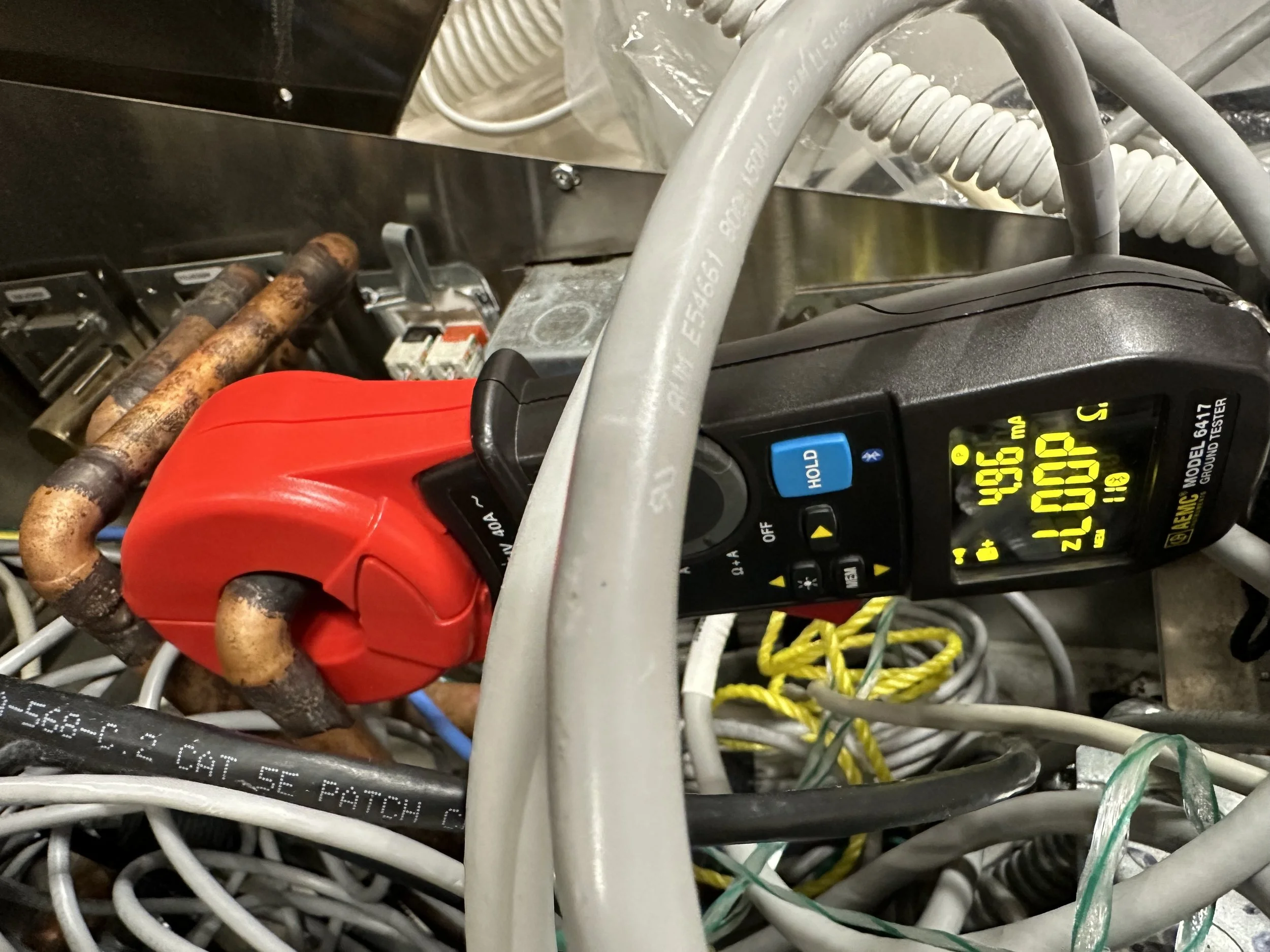
Advanced Measurement & Diagnostic Tools

  • Skilled use of near-field probes, current clamps, LISNs (line impedance stabilization networks), oscilloscopes, time-domain tools

  • Ability to interpret detailed measurement data, not just record it

Circuit-Level & System-Level Understanding

  • Ability to trace interference paths through PCBs, wiring, enclosures

  • Knowledge of how system design choices affect EMI performance

Knowledge of Compliance & Regulatory Requirements

  • Familiarity with specific test standards (FCC Part 15, CISPR 22, MIL-STD-461, RTCA/DO-160, etc.)

  • Understanding pre-compliance vs. full compliance testing requirements

Analytical & Problem-Solving Skills

  • Ability to hypothesize, isolate, and test root causes

  • Experience applying design fixes or mitigation solutions

Hands-On Engineering Skills

  • Sometimes requires circuit rework, adding ferrites, redesigning layouts, or modifying enclosures.

Required Skills & Knowledge for EMI Inspections

Core Knowledge Areas

  • Fundamentals of electromagnetic theory (fields, waves, coupling, shielding).

  • Understanding of electromagnetic compatibility (EMC) principles:

    • Emission control.

    • Susceptibility/immunity.

    • Shielding, filtering, grounding, and bonding.

  • Familiarity with cable management, enclosure design, and layout best practices.

  • Awareness of applicable EMI/EMC standards:

    • FCC Part 15 (commercial electronics, US).

    • IEC 61000 series (industrial and commercial EMC).

    • MIL-STD-461 (military EMI/EMC).

    • DO-160 (avionics EMI/EMC).

    • ISO 11452 or CISPR standards (automotive, industrial).

Practical Skills

  • Ability to visually assess EMI risks: grounding, shielding, cabling, and equipment layout.

  • Competence in using basic EMI measurement tools, if spot checks are included (spectrum analyzers, field meters, probes).

  • Skill in interpreting wiring diagrams, schematics, and floor plans.

  • Ability to write technical reports that document inspection findings and recommendations.

  • Understanding of risk assessment related to EMI in the specific operational context (IT systems, medical devices, communications systems, etc.).

Common Certifications (Optional but Valued)

While no license is legally required to perform EMI inspections, these certifications add credibility and are often requested by clients or employers:

  • Certified EMC Engineer (iNARTE EMC Engineer)
    International Association for Radio, Telecommunications, and Electromagnetics (iNARTE) certification, widely recognized in the EMC/EMI field.

  • Certified EMC Technician (iNARTE EMC Technician)
    A technician-level certification for those performing practical inspections and testing.

  • MIL-STD-461 Familiarization / Training Courses
    If working in the defense sector.

  • FCC Compliance Training
    Especially relevant for commercial electronics and telecom.

  • IEC/EN/ISO EMC Standards Training
    For industries governed by international EMC regulations.

Licenses (Generally Not Required)

  • In the US, no federal or state license is explicitly required for EMI inspections (unlike electrical contracting or professional engineering).

  • However, if your work crosses into engineering design or sign-off, a Professional Engineer (PE) license in electrical or RF engineering might be needed.

  • Depending on the site, a security clearance could be necessary for defense or aerospace projects.


Characterization of Each Type of EMI Service

Main Steps Involved in an EMI Survey

Define Survey Scope and Objectives

  • Identify what systems, equipment, or areas will be surveyed.

  • Clarify the purpose:

    • Baseline assessment of EMI environment.

    • Compliance check with standards (e.g., FCC, IEC, MIL-STD).

    • Investigation of suspected EMI problems.

    • Preparation for new equipment installation.

Review Background Information

  • Study site layouts, wiring diagrams, and shielding details.

  • Review any known EMI issues or prior reports.

  • Understand the types of equipment in use (medical devices, IT servers, industrial machinery, etc.).

Plan Measurement Setup

  • Select appropriate instruments:

    • Spectrum analyzers, EMI receivers, antennas, probes, and field strength meters.

  • Define:

    • Frequency ranges to cover.

    • Test points (locations, equipment under test).

    • Measurement modes (radiated vs. conducted).

Conduct On-Site Measurements

  • Perform radiated emission scans (airborne interference).

  • Perform conducted emission tests (interference on cables or power lines).

  • Identify external sources (e.g., nearby radio transmitters) and internal sources (e.g., switching power supplies, motors).

Analyze Data

  • Compare measurements to:

    • Regulatory limits.

    • Equipment susceptibility thresholds.

    • Environmental baselines.

  • Identify hot spots or areas where emissions approach or exceed limits.

Document Findings

  • Create detailed reports with:

    • Spectral plots.

    • Measurement data tables.

    • Maps or diagrams of EMI sources and affected areas.

  • Highlight:

    • Areas of compliance.

    • Areas of concern.

    • Recommended corrective actions or follow-up (if needed).

Provide Recommendations

  • Suggest mitigation strategies:

    • Improved grounding or shielding.

    • Use of filters or ferrites.

    • Equipment relocation.

  • Recommend whether further investigation (EMI troubleshooting) is necessary.

  • Where Is an EMI Survey Used?

  • Hospitals: Protect medical devices from RF and power line interference.

  • Data centers: Ensure the reliable operation of sensitive IT infrastructure.

  • Industrial plants: Prevent interference with robotics, control systems, or sensors.

  • Research labs: Preserve measurement accuracy and system stability.

  • Military/aerospace: Ensure mission-critical systems meet strict EMI/EMC performance.

What’s Not Typically Included?

  • Root-cause troubleshooting (belongs to an EMI investigation).

  • Complete certification testing (usually done in EMC test labs).

  • Permanent mitigation work (requires follow-up engineering or installation work).

Main Steps Involved in an EMI Investigation

Define the Problem Clearly

  • Identify and document:

    • The observed issue (e.g., system malfunction, data loss, communication failure, equipment reset).

    • When and where it occurs (specific times, locations, conditions).

    • The systems or devices are affected.

    • Any history of the problem or previous attempts to solve it.

Review Background Information

  • Gather:

    • System designs, schematics, and prior EMI/EMC reports.

    • Equipment manuals and susceptibility specs.

    • Environmental conditions (e.g., nearby transmitters, power disturbances, machinery).

Develop an Investigation Plan

  • Define:

    • What measurements are needed (radiated, conducted, near-field, time-domain).

    • The tools and instruments should be used (spectrum analyzers, oscilloscopes, TDRs, probes).

    • The test points and environmental factors to assess.

Conduct Targeted Measurements

  • Perform on-site tests to:

    • Identify EMI sources (external or internal).

    • Map interference paths (how it couples into sensitive systems).

    • Measure EMI levels vs. system susceptibility thresholds.

  • Use advanced techniques:

    • Near-field scanning, source localization.

    • Time-domain analysis of transient events.

    • Monitoring under different operating conditions.

Perform Root-Cause Analysis

  • Trace the exact mechanism causing the problem:

    • Is it radiated or conducted?

    • Common-mode or differential-mode coupling?

    • Ground loops, shielding failure, cable crosstalk, or parasitic coupling?

  • Correlate findings with system behavior.

Recommend Mitigations

  • Propose practical solutions, such as:

    • Shielding improvements.

    • Filter or ferrite installations.

    • Grounding or bonding adjustments.

    • Cable rerouting or equipment relocation.

    • Design modifications (if needed).

Validate Fixes (Optional but Ideal)

  • After applying fixes, re-measure and confirm that the interference problem is resolved.

Document the Investigation

  • Provide a detailed report with:

    • Description of the problem.

    • Measurement data and analysis.

    • Root-cause findings.

    • Recommended solutions and their technical basis.

    • Confirmation of resolution (if tested).

Where Are EMI Investigations Used?

  • Hospitals: When life-critical medical devices malfunction.

  • Data centers: When servers crash or communication links drop.

  • Industrial sites: When control systems or sensors behave unpredictably.

  • Military/aerospace: When mission-critical or safety-critical systems face unexplained disturbances.

  • Research labs: When precision instruments show unexplained noise or instability.

What’s Special About EMI Investigations?

  • Highly targeted — focus on solving an active or suspected interference problem.

  • More advanced tools and techniques — beyond general surveys or inspections.

  • It requires deep expertise and is often handled by senior EMI/EMC engineers or specialists.

  • Outcome-driven — the goal is not just to measure, but to explain, solve, and verify.


Aspects of an EMI Inspection

Visual Inspection

  • Check cable routing, grounding, and bonding practices.

  • Look for physical signs of EMI risks:

    • Poorly shielded enclosures or cables.

    • Loose or corroded grounding connections.

    • Unshielded or poorly isolated power and signal lines running together.

  • Inspect equipment racks, power panels, and interface connections.

Document and Design Review

  • Review design documents, wiring diagrams, and grounding layouts for EMI risks.

  • Verify compliance with standards (e.g., FCC Part 15, IEC 61000 series, MIL-STD-461 for military, or specific industry standards like TIA-942 for data centers).

Check Equipment and System Layout

  • Ensure sensitive equipment is positioned away from known EMI sources (like power transformers, radio transmitters, or industrial motors).

  • Verify the separation between power and signal lines.

  • Confirm that proper shielding and filtering components are installed where needed.

Spot Measurements (if needed)

  • Perform basic field strength checks at critical points if the inspection raises concerns.

  • Handheld meters can detect obvious emissions or coupling problems, but this is usually limited compared to a complete EMI survey.

Reporting and Recommendations

  • Document any risks or noncompliance areas.

  • Provide recommendations for mitigation, such as adding shielding, improving grounding, rerouting cables, or installing filters.

When Would You Perform an EMI Inspection?

  • During new installations, catch EMI risks before powering up.

  • As part of periodic maintenance or compliance audits.

  • When preparing for certification or regulatory approval.

  • Before a detailed EMI survey, to determine whether a full investigation is warranted.

  • After an EMI incident, as a first step before a deeper technical investigation.

    Common Certifications (Optional but Valued)

    While no license is legally required to perform EMI inspections, these certifications add credibility and are often requested by clients or employers:

    • Certified EMC Engineer (iNARTE EMC Engineer)
      International Association for Radio, Telecommunications, and Electromagnetics (iNARTE) certification, widely recognized in the EMC/EMI field.

    • Certified EMC Technician (iNARTE EMC Technician)
      A technician-level certification for those performing practical inspections and testing.

    • MIL-STD-461 Familiarization / Training Courses
      If working in the defense sector.

    • FCC Compliance Training
      Especially relevant for commercial electronics and telecom.

    • IEC/EN/ISO EMC Standards Training
      For industries governed by international EMC regulations.

    Licenses (Generally Not Required)

    • In the US, no federal or state license is explicitly required for EMI inspections (unlike electrical contracting or professional engineering).

    • However, if your work crosses into engineering design or sign-off, a Professional Engineer (PE) license in electrical or RF engineering might be needed.

    • Depending on the site, a security clearance could be necessary for defense or aerospace projects.

    • ©2025 All Rights are Reserved.

What Does an EMI Survey Cost in 2025?

The cost of an EMI survey can vary widely depending on several key factors, but I can give you some general ranges in an outline form to help set expectations.

Here’s a breakdown:

Typical EMI Survey Cost Range (U.S. dollars)

  • Small site or facility (single room, lab, small office):
    $2,000–$5,000 per survey

  • Medium site (entire floor, small industrial facility, data center section):
    $5,000–$15,000

  • Large or complex site (hospital, full industrial plant, large data center, military installation):
    $15,000–$50,000+

Cost Factors

The final price depends on:

  1. Scope of the survey: How much area, how many measurement points, and how many types of equipment are being surveyed.

  2. Duration: One-day survey vs. multi-day or long-term monitoring.

  3. Special requirements: Specialized equipment (high-frequency surveys, shielding assessments, etc.).

  4. Location: Travel costs if the survey team needs to come from another city or state.

  5. Reporting depth: A simple pass/fail report is cheaper than a complete technical analysis with mitigation recommendations.

What’s Typically Included

  1. Site visit and measurement campaign.

  2. Use of calibrated measurement equipment.

  3. Basic data analysis.

  4. Written report summarizing findings, often including maps or diagrams.

Additional costs may apply if you need:

  1. In-depth root-cause analysis (this leans into EMI investigation work)

  2. Detailed mitigation plans or engineering redesign support

  3. Compliance certification testing


©2025 All Rights are Reserved.