EMF, EMI, and EM Surveys - Their Differences and Purposes.

This article is about the differences between the three types of surveys involving electromagnetic radiation and the distinct purposes of each. These three types of surveys are:

1. Electromagnetic Field Radiation Surveys, EMF, or EMR;

2. Electromagnetic Interference Surveys, EMI, and

3. Electromagnetic Surveys, EM.

The tools used for each type will be discussed. 

Electromagnetic Field Radiation Survey (EMF Radiation Survey)

These surveys assess the electromagnetic radiation in the environment at a specified location.

Here is one of ELEXANA’s TEM cells inside of this Faraday cage.

  • The primary purpose of an EMF Survey is to assess human or equipment exposure to electromagnetic field radiation from power lines, cell towers, Wi-Fi, microwave ovens, etc.

  • EMF Surveys are used for occupational safety, regulatory compliance, health impact studies, and electronic equipment shielding. This shielding is usually for either radio frequency or AC magnetic field radiation from a source such as a transformer, electrical switch gear, conduit, or electrical closets.

  • Generally, EMF Surveys are conducted using portable meters that measure the strength of existing EM fields across various frequency bands. A good assessment covers the entire frequency range of the standard applied or a project’s requirements.

  • The tools often used for EMF Surveys are listed below.


Electromagnetic Interference (EMI) Survey

An electromagnetic interference survey is a scientific assessment of the unintended conductive and radiative emissions that interfere with the functioning of electronic devices or systems, to identify the sources of controlled and uncontrolled interference on the internal circuitry of the equipment from the local environment, and to assess whether this interference exceeds acceptable tolerance thresholds which could disrupt equipment or communication system function.

The essential measurements needed for an EMI assessment are:

1. Conducted emissions are harmonic transients, signal noise, traveling along cables, traces, power lines, etc.)

2. Radiated emissions are electromagnetic energies traveling through the air.

Subsets of these emissions are:

A. Inductive Coupling is magnetic field energy generated by current, and the transients are coupled with the magnetic field’s fundamental. In the case of an AC magnetic field in the USA, this fundamental is 60 Hertz. In Europe, the fundamental is 50 Hertz.

B. Capacitive Coupling is electric field energy generated by a voltage, potential, and the transients are coupled with the electric field’s fundamental. An AC electric field in the USA has a fundamental frequency of 60 Hertz. In Europe, the fundamental is 50 Hertz.


Common reasons why someone would want an EMI survey are:

  1. Aerospace and defense systems (shielding effectiveness).

  2. Medical devices (ensuring hospital equipment is restored to normal function).

  3. Industrial or communication sites (preventing signal loss or distortion).


Electromagnetic Field (EMF) Radiation Survey

An EMF survey measures the strength and presence of various electromagnetic field radiation in an environment, typically to assess human exposure levels. In the US, guideline levels for human exposure are found in Bulletin OET-65.

An EMF survey aims to ensure compliance with health and safety regulations related to EMF exposure, not necessarily to address equipment interference.

Essential measurements and their units are:

  1. Electric fields (V/m: Voltage per meter).

  2. Magnetic fields (A/m, µT, or mG: Amperes per meter, microTeslas, or milliGauss).

  3. Power density (W/m², W/cm²: Watts per square meter or square centimeter across various frequency bands).

The general applications for an EMF survey are:

  1. Assessing radiation from power lines, cellular towers, Wi-Fi routers, and electrical wiring and equipment.

  2. Workplace or residential safety evaluations.

  3. Environmental impact assessments.


Electromagnetic Survey (EM Survey)

EM surveys are used in geophysics and subsurface exploration.

  1. The reason for conducting an EM survey is to detect variations in the ground’s electrical conductivity and magnetic permeability.

  2. These surveys are used for mineral exploration, groundwater mapping, environmental site assessment, and locating buried objects.

  3. Instruments send or inject electromagnetic signals into the ground; the response (secondary fields) is measured to infer what’s underground.

  4. Time-domain EM systems and frequency-domain EM instruments are used for EM surveys.


The main difference among the three types of surveys is:

  • EMF surveys focus on whether electromagnetic fields affect human health and safety.

  • EMI surveys focus on whether electromagnetic emissions may disrupt equipment and systems.

  • EM surveys focus on locating what is below Earth’s surface.

The Tools Used for Different Surveys

While electromagnetic interference (EMI) surveys, electromagnetic field (EMF) radiation surveys, and electromagnetic surveys (EM) deal with electromagnetic phenomena, they have different goals and use other tools.

Electromagnetic Field (EMF) Radiation Survey

  1. The aim is to measure electromagnetic field levels to assess human exposure or environmental impact, often for health, safety, or regulatory compliance (e.g., near cell towers, power lines, or industrial equipment).

  2. The standard equipment used for measuring EMF is:

  • Broadband EMF meters — handheld devices that measure field strength across a wide frequency range, usually giving total field strength (V/m, A/m, W/m²).

  • Gaussmeters or magnetometers — to measure static or low-frequency magnetic fields.

  • Electric field meters — to measure static or low-frequency electric fields.

  • Isotropic probes — sensors that capture field strength from all directions, 360º. These are essential for assessing human exposure.

  • Personal EMF dosimeters are generally wearable devices for logging individual exposure over time.

    These tools are adept at measuring field strength levels, time-averaged exposure, and safety compliance with limits set by agencies like the FCC, ICNIRP, IEEE, or national health guidelines.


Electromagnetic Interference (EMI) Survey

  1. The aim is to identify, locate, and quantify sources of electromagnetic noise that interfere with the operation of electronic devices or systems (e.g., computers, radios, avionics, medical equipment). (Please note: At Elexana, we take this one more step to troubleshoot for optimal solutions that further suit our clients’ needs and budget. Often, the survey will include the solutions.

  2. Typical Tools:

    1. Spectrum analyzers — measure signal levels over various frequency bands and help detect interference sources.

    2. EMI receivers are specialized equipment that measure conducted and radiated emissions. They are compliant with standards (like CISPR and MIL-STD).

    3. Near-field probes — handheld probes (magnetic and electric) for local “sniffing” near circuit boards or cables.

    4. Current clamps are used to measure noise on power or signal lines.

    5. Anechoic chambers are shielded rooms designed to prevent outside EM signals and reflections.

    6. Portable TEM cells are impedance-balanced transverse electromagnetic enclosures, usually within a Faraday cage, that serve a similar purpose to an anechoic chamber.

  3. An EMI survey focuses on specific frequency bands, transient signals, narrowband or broadband interference, and compliance with regulatory limits (e.g., FCC, CISPR).

Electromagnetic (EM) Survey

  1. Time-domain electromagnetic (TDEM) Systems- Inject pulsed EM fields into the ground and measure transient responses over time.

    Specific tools: Geonics PROTEM, Zonge GDP-32, ABEM WalkTEM

  2. Frequency-Domain Electromagnetic (FDEM) Systems - Transmit continuous EM waves at multiple frequencies, measure ground conductivity.

    Tools: Geonics EM31, EM34, EM38, DualEM-421, GEM-2 by Geophex

  3. Controlled-Source Audio Magnetotellurics (CSAMT) - Use an artificial EM source to probe deeper structures, combining electric and magnetic field data.

    Tools: Zonge CSAMT, Phoenix Geophysics systems

  4. Magnetotelluric (MT) Systems—These passive systems use natural EM signals from lightning and solar activity to probe the deep earth.

    Tools: Phoenix MTU-5A, Quantec Spartan MT

  5. Ground Conductivity Meters: Handheld or portable devices for shallow surveys, often for environmental or agricultural work.

    Tools: Geonics EM38, EM31; CMD Explorer

  6. Loop and Coil Sensors (Transmitter/Receiver Coils) - Transmit and receive EM signals; vary in size for shallow or deep penetration.

    Tools: Custom loop setups with induction coils.

  7. Resistivity and Induced Polarization (IP) Systems. - While not strictly EM, it is often combined to measure resistivity and chargeability alongside EM surveys,

    Tools: IRIS Syscal Pro, ABEM Terrameter

  8. Data Logging and Processing Software: - Specialized software to model subsurface conductivity from collected EM data.

    Tools: EMIGMA, Maxwell, Res2DInv, Aarhus Workbench.


Elexana LLC is recognized globally as a top-tier Electromagnetic Interference (EMI) site survey provider due to its comprehensive approach, technical expertise, and commitment to client-centric solutions.

©2025 All Rights are Reserved.

Geothermal Power: Common Questions Answered, Including Electromagnetic Interference Concerns


Home Geothermal System 1. Photo by James Finn ©2023

The first practical geothermal question most people ask me is, “How deep and wide does the hole need to be dug for a home geothermal system?”

Here’s my answer: The depth and width of the hole that needs to be dug for a home geothermal system will depend on several factors, including:

  1. Type of system: There are two main types of geothermal systems for homes: ground-source heat pump systems and direct-use geothermal systems. The depth and width of the hole will depend on the type of system you choose.

  2. Climate: The depth and width of the hole will also depend on your local climate and the average temperature of the ground at your location. In colder climates, the hole may need to be deeper to access warmer ground.

  3. Soil conditions: The soil conditions at your location will also play a role in determining the depth and width of the hole. For example, if you have rocky or sandy soil, the hole may need to be wider to accommodate the installation of the pipes.

  4. System size: The size of the geothermal system you choose will also impact the depth and width of the hole. Larger systems will typically require deeper and wider holes to accommodate the increased number of pipes and other components.

Home Geothermal System 2. Photo by James Finn ©2023

As a general rule, a home geothermal system typically requires a hole that is between 100 and 400 feet deep and between 4 and 6 inches in diameter. However, these are rough estimates, and the exact depth and width of the hole will depend on the specific conditions at your location and the type of geothermal system you choose.

It is recommended that you work with a licensed and experienced geothermal contractor who can assess your specific needs and provide an accurate estimate of the depth and width of the hole required for your home geothermal system.


Geothermal power systems for homes typically use the constant temperature of the earth as a source of energy to heat and cool a building. There are two main types of geothermal power systems for homes: ground-source heat pump systems and direct-use geothermal systems.

  1. Ground-Source Heat Pump Systems: These systems use a heat pump to transfer heat between the home and the ground. The system consists of a ground loop (a series of pipes buried in the ground), a heat pump unit inside the home, and a distribution system (e.g., ducts or radiant flooring) to distribute the heat.

Components:

  • Ground loop

  • Heat pump unit

  • Distribution system

Pros:

  • Energy efficient: Ground-source heat pump systems are typically more efficient than traditional heating and cooling systems.

  • Renewable energy: Geothermal energy is a renewable resource, so these systems reduce reliance on non-renewable energy sources.

  • Long lifespan: Ground-source heat pump systems have a long lifespan and require little maintenance.

Cons:

  • High upfront cost: The initial cost of installing a ground-source heat pump system can be high.

  • Limited availability: Geothermal resources are not available everywhere, so these systems may not be suitable for all locations.

Costs:

  • Purchase cost: Ground-source heat pump systems typically cost between $7,500 and $25,000, depending on the size and complexity of the system.

  • Installation cost: Installation costs can range from $10,000 to $25,000, depending on the complexity of the installation and local labor costs.


    2. Direct Use Geothermal Systems: These systems use hot water from geothermal wells or springs to directly heat a building. The hot water is typically piped directly into the building and used for heating, hot water, and/or industrial processes.

Components:

  • Geothermal well or spring

  • Piping system

  • Heat exchanger

Pros:

  • Direct use of hot water: Direct use geothermal systems use hot water directly, which can be more energy efficient than using a heat pump.

  • Suitable for certain locations: Direct-use geothermal systems are best suited to locations with hot water resources.

Cons:

  • Limited availability: Geothermal resources are not available everywhere, so these systems may not be suitable for all locations.

  • High upfront cost: The initial cost of installing a direct-use geothermal system can be high.

Costs:

  • Purchase cost: Direct-use geothermal systems typically cost between $10,000 and $50,000, depending on the size and complexity of the system.

  • Installation cost: Installation costs can range from $15,000 to $50,000, depending on the complexity of the installation and local labor costs.

These are the main types of geothermal power systems for homes, along with some of their components, pros, cons, and costs. It's important to note that the actual costs and feasibility of these systems can vary greatly depending on local factors such as climate, geology, and regulations.

Home Geothermal System 3. Photo by James Finn ©2023


Here is more detail on the components of a ground-source heat pump system:

  1. Ground Loop: The ground loop is a series of pipes that are buried in the ground near the home. The pipes are filled with a water-based solution (or refrigerant in some cases) that transfers heat to or from the ground, depending on the desired heating or cooling effect. There are two main types of ground loops: horizontal loops and vertical loops. Horizontal loops are typically used for residential systems and are installed by digging trenches in the ground. Vertical loops are typically used for commercial systems and are installed by drilling wells into the ground.

  2. Heat Pump Unit: The heat pump unit is located inside the home and is responsible for transferring heat between the ground loop and the home. The unit consists of a compressor, a heat exchanger, and an expansion valve. The heat pump unit works by compressing the refrigerant in the heat exchanger to increase its temperature and then transferring the heat to the home through the distribution system.

  3. Distribution System: The distribution system is responsible for distributing the heat (or cooled air) throughout the home. This can be done through ducts and air handlers (for forced air systems) or through radiant flooring or radiators (for hydronic systems). The distribution system is designed to maximize the efficiency of the heat pump unit and ensure that the heat is evenly distributed throughout the home.

These are the main components of a ground-source heat pump system, and they work together to provide efficient heating and cooling for a home. It's important to note that there are many different designs and configurations of heat pump systems, and the specific components and design of a system will depend on factors such as the size of the home, local climate, and the preferences of the homeowner.


Home Geothermal System 4. Photo by James Finn ©2023

Ground-source heat pump systems utilize the consistent temperature of the ground to heat and cool a home efficiently. A network of underground pipes circulates a mixture of water and antifreeze, which transfers heat to or from the home as needed. This system is highly energy efficient and can also provide hot water.

Direct-use geothermal systems use the naturally warm water from geothermal wells for heating and sometimes for producing hot water. This water is pumped directly into the home and does not require any heat exchange. This system is ideal for homes located near geothermal wells and is often used for radiant floor heating and hot water heating.


What are the pros and cons of a Direct-use geothermal system?


Pros:

  • High Efficiency: Direct-use geothermal systems utilize natural heat from the earth, making them highly efficient and reducing energy consumption and costs.

  • Reliable: This type of system is very reliable as it does not rely on any external energy source, such as fuel or electricity.

  • Environmentally Friendly: Direct-use geothermal systems do not produce any greenhouse gas emissions, making them a clean and environmentally friendly option.

  • Low Maintenance: This type of system requires minimal maintenance, as it does not have any moving parts and operates underground.

Cons:

  • Limited Availability: Direct-use geothermal systems are only feasible in certain areas where geothermal wells are accessible, and the water is warm enough for heating purposes.

  • High Initial Cost: The cost of drilling a geothermal well can be high, making the initial investment for a direct-use geothermal system relatively high.

  • Limited Functionality: Direct-use geothermal systems are only used for heating and hot water, whereas a ground-source heat pump system can also provide cooling.

  • Well Drilling Risks: The process of drilling a geothermal well carries some risks, such as the potential release of harmful gases or the contamination of underground water sources.


The cost of a direct-use geothermal system can vary greatly depending on several factors, such as the location, size of the home, and the complexity of the installation.

Equipment costs:

  • Geothermal Well: The cost of drilling a geothermal well can range from $10,000 to $30,000 or more, depending on the depth and location.

  • Heat Pump: A heat pump is required to circulate the warm water from the well to the home, and its cost can range from $2,500 to $7,500.

  • Pipes and Insulation: The cost of pipes and insulation can vary, but it can be around $1,500 to $4,000.

Installation costs:

  • Installation of the well, heat pump, and pipes can cost between $20,000 to $50,000 or more, depending on the complexity of the project and the location.

It is important to note that these costs can vary greatly and that it is always best to get a detailed quote from a qualified geothermal contractor. Additionally, the high initial cost of a direct-use geothermal system is often offset by long-term energy savings and low maintenance costs.


Heat Pump:

A heat pump is a central component of a direct-use geothermal system. It circulates the warm water from the geothermal well to the home and is responsible for extracting heat from the water and transferring it to the home for heating purposes. Heat pumps come in different sizes and configurations, but the most common types used in direct-use geothermal systems are air-source and water-source heat pumps.

Air-source heat pumps use the outdoor air as the source of heat, while water-source heat pumps use the water from the geothermal well. Both types of heat pumps work by using a refrigerant to transfer heat from one location to another. In the case of a direct-use geothermal system, the heat pump circulates warm water from the well to the home and transfers heat to the home's heating system.

Pipe Insulation:

Pipe insulation is used in a direct-use geothermal system to prevent heat loss as the water is circulated from the geothermal well to the home. The insulation helps to keep the water at a consistent temperature, which improves the efficiency of the system and reduces energy consumption.


There are different types of insulation materials available, including foam insulation, fiberglass insulation, and closed-cell insulation. The type of insulation used will depend on the specific requirements of the system and the local building codes. It is important to use high-quality insulation that is designed for underground use, as it must be able to withstand the harsh conditions of underground installation.

Several types of foam insulation can be used for underground pipes in a direct-use geothermal system, including polyurethane foam and polyethylene foam.


Polyurethane foam is a closed-cell foam that is known for its high insulation value, durability, and resistance to moisture. It is often used for underground pipe insulation due to its excellent thermal performance and ability to withstand the pressure of the surrounding soil.

Polyethylene foam is another common choice for underground pipe insulation. It is a lightweight, flexible, and closed-cell foam that is easy to install and provides good insulation properties. It is also resistant to moisture and has a low thermal conductivity, which makes it a good choice for geothermal applications.

The type of foam insulation used in a direct-use geothermal system will depend on several factors, such as the local building codes, the climate, and the specific requirements of the system. It is best to consult with a professional geothermal contractor to determine the most appropriate type of insulation for your system.


Closed-cell insulation is a type of insulation material that is made up of small, tightly packed cells that are filled with a gas, such as air, or a proprietary blend of gases. The cells are closed, meaning that the gas is trapped inside and cannot circulate freely, providing excellent insulation properties.

Closed-cell insulation is known for its high insulation value, making it a good choice for applications where high thermal performance is required. It is also resistant to moisture, which makes it a good choice for underground installations, such as in a direct-use geothermal system.

Closed-cell insulation is typically denser and stiffer than open-cell insulation, making it a good choice for applications where structural support is required. Additionally, because the cells are closed, it has a higher resistance to air infiltration and can provide a vapor barrier, making it a good choice for applications where airtightness is important.


Overall, closed-cell insulation is a versatile and effective insulation material that is widely used in a variety of applications, including building and construction, industrial and commercial applications, and geothermal systems.


The type of gas used in closed-cell insulation can vary depending on the manufacturer and the specific product. Some of the most common gases used in closed-cell insulation include:

  • Air: Air is the most common gas used in closed-cell insulation and is often used in polyurethane foam insulation.

  • Argon: Argon is an inert, colorless, and odorless gas that is often used in closed-cell insulation due to its excellent insulation properties.

  • Krypton: Krypton is another inert gas that is often used in closed-cell insulation due to its high thermal resistance.

  • Xenon: Xenon is a rare, inert gas that is used in closed-cell insulation due to its high thermal resistance and insulation value.


It is important to note that some manufacturers use proprietary blends of gases to enhance the insulation properties of their products. These blends can be optimized to provide the best combination of insulation value, moisture resistance, and durability.

The specific gas used in closed-cell insulation will depend on the manufacturer, the product, and the specific requirements of the application. Consult with a professional insulation specialist to determine the best type of gas for your needs.


What are the potential hazards of using geothermal energy production?


Yes, there are potential hazards associated with geothermal energy production, although these are generally minor compared to the benefits of this clean, renewable energy source. Some of the most common hazards include:

  • Hydrogen Sulfide Gas: Hydrogen sulfide gas is a byproduct of geothermal energy production and can pose a health risk if not properly managed. In high concentrations, hydrogen sulfide gas can be toxic and can cause respiratory problems, headaches, and dizziness. It is important to install proper ventilation systems and monitor hydrogen sulfide levels to ensure the safe operation of a geothermal energy system.

  • Earth Tremors: Geothermal energy production can sometimes cause small earth tremors, although these are generally minor and do not pose a significant risk. In some cases, geothermal energy production has been associated with increased seismic activity, although this is relatively rare.

  • Environmental Impacts: Geothermal energy production can have impacts on the local environment, including changes to water quality, soil and air quality, and wildlife habitats. It is important to carefully manage and monitor these impacts to ensure that geothermal energy production is sustainable over the long term.

  • Corrosion: Geothermal energy production can result in increased levels of corrosion, which can affect the longevity and performance of equipment and infrastructure. It is important to use corrosion-resistant materials and coatings to prevent this type of damage.

Overall, geothermal energy production is considered to be a relatively safe and environmentally friendly form of energy production, and the hazards associated with this technology are manageable with proper planning and management.


Here are a few companies that install geothermal systems for homes in the Dallas, Texas area:

  1. EcoGeo Solutions

  2. TGE Technologies

  3. Skyline Innovations

  4. Green Energy Solutions

  5. Prime Mechanical

  6. Texas Geothermal Solutions

  7. H&H Environmental Services

  8. Texas Renewable Energy

  9. WaterFurnace Southwest

  10. Earth Energy Solutions


Here are a few companies that install geothermal systems for homes in the New York Tristate area:

  1. Advanced Geothermal Systems

  2. Geothermal Experts

  3. Tri-State Geothermal

  4. Earth Energy Solutions

  5. Green Energy Solutions

  6. Energy Geothermal

  7. Infinity Renewables

  8. Climate Control Heating & Air Conditioning

  9. Naughton Energy

  10. R.A. Snyder Services


Here are a few companies that install geothermal systems for homes in the Los Angeles, California area:


  1. Cal-Tech Heating & Air Conditioning

  2. California Geothermal

  3. Geo-Thermal Solutions

  4. Green Energy Solutions

  5. Sunset Air

  6. SoCal Geothermal

  7. Energy Geothermal

  8. Infinity Renewables

  9. EcoGeo Solutions

  10. LA Geothermal Solutions


It is important to note that this list is not exhaustive, and there may be other companies in these areas that offer geothermal installation services. Before choosing a company, it is recommended that you research their experience and reputation and get multiple quotes to compare prices and services. Additionally, it is recommended that you work with a licensed and insured contractor to ensure the quality and safety of your geothermal system installation.


Here are some potential drawbacks of using geothermal energy for a home:

  1. Initial Costs: Installing a geothermal energy system can be expensive, with costs ranging from $20,000 to $50,000 or more. This may make it less accessible for some homeowners, especially those on a tight budget.

  2. Complexity: Geothermal systems are complex and require specialized knowledge and skills to install and maintain. This can make it difficult for homeowners to perform their own maintenance or repairs and may require them to hire a professional contractor.

  3. Location-specific: Geothermal energy systems require access to geothermal resources, such as hot springs, geysers, or volcanic activity. This means that not all homes will be able to use geothermal energy, and the suitability of the technology will depend on the local geography and geology.

  4. Limited Capacity: Some geothermal systems may have limited capacity and may not be able to generate enough energy to power a home during periods of high demand.

  5. Environmental Concerns: Geothermal energy systems can have some environmental impacts, such as the release of greenhouse gases and changes to water quality in the vicinity of geothermal wells. Additionally, the installation of geothermal systems may result in the disturbance of natural landscapes, including the removal of vegetation and the excavation of land.

It is important to note that these potential drawbacks will vary depending on the specific system, location, and other factors. Before choosing a geothermal energy system, it is important to carefully consider the costs, benefits, and potential drawbacks of the technology and to work with a licensed and experienced contractor to ensure the quality and safety of your installation.


Here are some long-term benefits of using geothermal energy to power a home:

  1. Energy Efficiency: Geothermal systems are highly energy efficient, with efficiency ratings that can be as high as 400%. This means that they can generate more energy than they consume, reducing the amount of energy required from other sources.

  2. Cost Savings: Geothermal systems can result in significant cost savings over time, as homeowners can reduce their dependence on more expensive forms of energy, such as electricity from the grid or heating oil.

  3. Reliability: Geothermal systems are reliable and can provide consistent and continuous heating and cooling with minimal maintenance. This means that homeowners can count on their systems to keep their homes comfortable and energy efficient, even during periods of extreme weather or power outages.

  4. Environmentally Friendly: Geothermal systems are considered to be environmentally friendly, as they produce very low emissions of greenhouse gases and do not rely on the burning of fossil fuels.

  5. Longevity: Geothermal systems are long-lasting and can last for decades with proper maintenance. This makes them a smart investment for homeowners who want to reduce their energy costs and minimize their environmental impact over the long term.


It is important to note that the specific benefits of using geothermal energy to power a home will depend on the specific system, location, and other factors. Before choosing a geothermal energy system, it is important to carefully consider the costs, benefits, and potential drawbacks of the technology and to work with a licensed and experienced contractor to ensure the quality and safety of your installation.


What are the potential electromagnetic issues with using geothermal power for a home?


There are no significant electromagnetic issues associated with using geothermal power for a home. Geothermal systems work by tapping into the heat stored in the earth to provide heating, cooling, and hot water for a home. Unlike other types of energy generation, such as fossil fuels or nuclear power, geothermal systems do not generate significant levels of electromagnetic radiation or interference.

It is important to note that all electrical equipment, including geothermal systems, generates some level of electromagnetic interference, but these levels are typically well within safe limits and do not pose a significant risk to human health or the environment. If you have concerns about electromagnetic interference from your geothermal system, you can work with a licensed and experienced contractor to assess the system and make any necessary modifications to ensure that it operates safely and efficiently.


Are inverters needed to convert DC to AC with geothermal systems?


Inverters are not typically needed with geothermal systems. Geothermal systems work by tapping into the heat stored in the earth to provide heating, cooling, and hot water for a home. Unlike solar panels, which generate electricity from the sun, geothermal systems do not generate electricity and do not require inverters to convert DC to AC.

Instead, geothermal systems use a heat pump to transfer heat from the earth to the home, where it is used to provide heating, cooling, and hot water. The heat pump operates using electrical power, but it does not generate electricity and, therefore, does not require an inverter.

If you are interested in using geothermal energy to power your home, it is important to work with a licensed and experienced contractor who can help you assess your specific energy needs and determine the best type of geothermal system for your home. They can also provide information on any additional equipment or components that may be needed to ensure the safe and efficient operation of your geothermal system.


Does the heat pump use a Variable Frequency Drive?


Yes, some geothermal heat pumps use a Variable Frequency Drive (VFD) to control the speed of the system's compressor and circulate refrigerant. The VFD helps to regulate the flow of refrigerant, which in turn helps to optimize the efficiency of the heat pump and reduce energy consumption.

VFDs can also be used to control the speed of the system's fan or pump, depending on the specific design of the heat pump. By using a VFD, the heat pump can operate at an optimal speed to meet the demands of the heating and cooling system, which can help to improve efficiency and reduce energy consumption.

It is important to note that not all geothermal heat pumps use a VFD, and the use of a VFD is dependent on the specific design of the heat pump. If you are interested in using a geothermal heat pump with a VFD, it is recommended that you work with a licensed and experienced contractor who can provide information on the specific heat pump and assist with the installation and operation of the system.


Does the VFD produce EMI?


Variable Frequency Drives (VFDs) can produce Electromagnetic Interference (EMI). EMI is the result of electrical and magnetic fields that are generated by electrical equipment and can interfere with other electronic equipment or devices.

In the case of VFDs, the fast switching of the power electronics within the VFD can generate EMI, which can affect other electronic equipment or devices in the vicinity. However, most VFDs are designed with EMI filtering to reduce the level of interference, and modern VFDs are typically well within the limits established by international standards for EMI.


If you are concerned about the potential for EMI from a VFD in your geothermal heat pump system, it is recommended that you work with an experienced EMI Consultant who can assess the specific VFD and make any necessary modifications to ensure that it operates safely and efficiently. They can also provide information on any additional equipment or components that may be needed to reduce the level of EMI from the VFD.


What are the typical frequencies of variable Frequency Drives for geothermal heat pumps?


The typical frequency range for a Variable Frequency Drive (VFD) in a geothermal heat pump system is between 0 and 60 Hertz (Hz). The exact frequency range of a VFD will depend on the specific design and requirements of the geothermal heat pump system.

The VFD is used to control the speed of the system's compressor or fan, which helps to regulate the flow of refrigerant or air within the heat pump. By adjusting the frequency of the VFD, the speed of the compressor or fan can be increased or decreased as needed, which in turn helps to optimize the performance of the heat pump.

It is important to note that different geothermal heat pump systems may use VFDs with different frequency ranges, and the frequency range of the VFD will depend on the specific design of the heat pump system. If you are interested in using a geothermal heat pump with a VFD, it is recommended that you work with a licensed and experienced contractor who can provide information on the specific VFD and assist with the installation and operation of the system.

Solar Power Inverters and EMI Filtering Techniques; Everything You Need to Know

Whether you are an electrical engineer, an electrician, or a homeowner considering a new solar power system installation, or you already own one, you will eventually need to deal with the resultant electromagnetic interference, EMI.

Regardless of the term you prefer, Signal-to-Noise Ratio (S/N or SNR), THD+N (Total Harmonic Distortion Plus Noise), harmonic transients, ripple, or “dirty electricity,” solar systems emit high amplitudes of transient harmonic voltages from semiconductor switching onto an electrical system, often interfering to varying degrees with the function of your appliances, electrical devices, electronics, and, eventually onto you.

(The basic physics formulas that describe this process are: Δv/Δτ and Δi/Δτ, where Δ = change, τ = time interval, v = voltage differences, i = current differences.)

Alternative energy is now more popular than ever, and there is much to learn. In the next few months, I plan to share essential knowledge about each type and how to mitigate the electromagnetic interference they produce.

Solar Power is by far the alternative energy source most often asked about. Solar panels produce direct current (DC) electricity, which is incompatible with the alternating current (AC) electricity used in homes. To use the electricity produced by solar panels, it must be converted from DC to AC.

Here is the basic process to convert solar energy into usable AC electricity for a home:

  1. Sunlight: The sun provides the energy source for the solar photovoltaic cells.

  2. Solar Photovoltaic Cells: The photovoltaic cells within a series of photovoltaic (PV) panels are installed on the roof or in a suitable location with unobstructed access to sunlight. The panels convert the sunlight into direct current (DC) electricity.

  3. DC to AC Inverter: The DC electricity from the panels is sent to a solar inverter, which converts the DC electricity into alternating current (AC) electricity. The inverter is typically located near the electrical service panel in the home.

  4. Electrical Service Panel: The AC electricity is then sent to the home's electrical service panel, which is then distributed to the various electrical branch circuits in the home.

  5. Energy Metering: A bi-directional meter is installed to monitor the flow of electricity between the home and the electrical grid. This meter allows the homeowner to determine how much electricity is being produced by the solar panels and how much is being drawn from the grid.

  6. Electrical Grid Connection: The home is connected to the electrical grid through a power company-owned utility line. This allows the home to receive electricity from the grid when the demand exceeds the supply from the solar panels and to send excess electricity back to the grid when the panels are producing more electricity than the home is using.

  7. ESS: (Energy Storage System) is a device that stores excess energy generated by a solar power system. The stored energy can be used later to meet the energy demand when the solar panels are not producing enough energy (e.g., during nighttime or cloudy conditions). An ESS typically consists of batteries or other energy storage technologies and may include power electronics and control systems. Using an ESS can increase the overall efficiency of a solar power system and provide a more reliable and stable energy supply.

    Some popular brands and models of ESS for home use:

    • Tesla Powerwall: This is a lithium-ion battery system designed for residential use and is one of the most well-known ESSs on the market.

    • LG Chem RESU: This is a high-capacity lithium-ion battery system compatible with a wide range of inverters and can be easily integrated into a home solar power system.

    • Sonnen: Sonnen offers several ESS models for residential use, including the SonnenBatterie and the SonnenCore. These systems are designed to work in tandem with solar panels and provide energy storage and backup power.

    • Enphase Energy Storage System: This is a modular battery system that can be added to an existing Enphase solar power system. It uses lithium-ion batteries and has a scalable design, making it suitable for homes of different sizes.

    These are just a few examples of ESSs that are available for residential use. When choosing an ESS for your home, it's important to consider factors such as capacity, compatibility with your existing solar power system, and the local regulations and incentives for energy storage.

(A licensed electrical contractor should be consulted for a detailed design and installation to ensure compliance with local codes and standards.)

The conversion process is accomplished by using an inverter. An inverter takes the DC electricity from the solar panels and converts it into AC electricity. The inverter is usually installed near the solar panels and is connected to the panels through cables. The DC electricity from the panels flows into the inverter and is then converted into AC electricity.

When choosing an inverter, it is important to consider the following factors:

  1. Power capacity: The inverter must have the capacity to handle the amount of electricity produced by the solar panels.

  2. Efficiency: An efficient inverter will produce less heat and more efficiently convert DC to AC electricity.

  3. Grid compatibility: Inverters are designed to be compatible with the electrical grid in your area. It is important to choose an inverter that is compatible with your local electrical grid.

  4. Size: The inverter must be appropriately sized for the amount of electricity produced by the solar panels.

By converting DC solar to AC electricity, homes can use the clean and renewable energy produced by their solar panels to power their homes. This not only reduces their carbon footprint but also saves on electricity costs.

Reducing line noise or Electromagnetic Interference (EMI) is integral to the DC-to-AC conversion process.

Here are a few steps that can be taken to reduce EMI:

  1. Proper grounding: Ensure that the inverter is properly grounded to minimize the risk of EMI.

  2. Quality components: Use high-quality components in the inverter circuit to reduce EMI.

  3. Shielding: Shield the inverter and cables with metal casing or braided shielding to reduce the emission of EMI.

  4. Ferrite beads: Place ferrite beads on the DC and AC cables to absorb EMI.

  5. Filtering: Implement appropriate filtering in the inverter circuit to reduce EMI.

  6. Proper installation of the inverter and cables will also reduce EMI.

Reducing EMI is important to ensure that the electrical system remains stable and does not interfere with other electrical equipment. By taking these steps, you can reduce the risk of EMI and ensure that your DC to AC-conversion process is efficient and reliable.

Here are a few EMI filters commonly used in DC to AC conversion applications:

  • Common-Mode Choke: A common-mode choke is a type of inductor placed on the DC and AC cables to absorb EMI. It is typically used in pairs, one placed on the positive line and one on the negative line, to reduce the common-mode noise on both lines. The choke consists of a wire coil wound around a magnetic core. The magnetic core is designed to increase the coil's inductance, which helps reduce the flow of high-frequency noise.

    A common-mode choke provides a low impedance path for the common-mode noise, which helps reduce the amount of noise transmitted from the power source to the equipment. The choke acts as a filter, absorbing the high-frequency noise and reducing the amount of EMI in the system.

    Common-mode chokes are a simple, effective, and reliable solution for reducing EMI in electrical systems and are widely used in various applications, such as DC to AC power inverters, power supplies, and motor drives. They are particularly useful in applications with high common-mode noise, providing a cost-effective solution for reducing this noise.

  • Pi Filter: A Pi filter is a type of LC filter placed on the AC output of the inverter to reduce EMI. It is a passive circuit that consists of two inductors (L) and two capacitors (C) arranged in a Pi configuration.

    The Pi filter works by reducing high-frequency noise in the system. The inductors act as choke coils, limiting the flow of high-frequency noise, while the capacitors act as bypasses, short-circuiting the high-frequency noise and passing it to ground.

    The Pi filter is often used in applications where the requirement for EMI reduction is high, such as in DC to AC power inverters, power supplies, and motor drives. The Pi filter can be customized to meet the application's specific requirements, such as the frequency range and the level of EMI reduction required.

    The Pi filter is a simple, cost-effective, and reliable solution for reducing EMI in electronic systems. It is widely used in various applications and is considered a standard solution for EMI reduction.

  • Common-Mode Filter: A common-mode filter is a type of filter that is placed on the AC output of the inverter to reduce EMI. A common-mode filter is an EMI (Electromagnetic Interference) filter used to suppress common-mode noise in electrical systems. It works by suppressing the differential-mode noise and passing the common-mode noise through capacitors and inductors.

    The components of a common-mode filter include:

    • Chokes (Inductors): These components limit the flow of high-frequency noise.

    • Capacitors: These components provide a low-impedance path to ground for high-frequency noise.

    • Ferrite Beads: These components act as high-frequency low-pass filters and provide additional EMI suppression.

    The common-mode filter is connected in parallel with the power or signal lines to be protected, with the positive side connected to one line and the negative side connected to the other line. The combination of inductors and capacitors in the filter creates a low-impedance path for common-mode noise, effectively filtering it out of the signal.

  • Line Filter: A line filter is an EMI filter placed on the AC input of the inverter to reduce EMI. These filters can be selected based on the specific requirements of the application, such as the amount of EMI reduction required, the type of electrical equipment that needs to be protected, and the cost and availability of the filters. Usually, a combination of these filters is used to achieve the desired level of EMI reduction.

    A line filter is typically placed between the power source and the equipment being powered to reduce the amount of high-frequency noise transmitted from the power source to the equipment. Line filters are an effective and reliable solution for reducing EMI in electrical systems and are widely used in various applications.

A typical Line Filter consists of the following components:

  1. Inductor(s): One or more inductors are used to limit the flow of high-frequency noise, which acts as a choke coil.

  2. Capacitor(s): One or more capacitors are used to short-circuit the high-frequency noise, which acts as a bypass.

  3. Resistor(s): One or more resistors are used to provide damping to the filter, which helps to reduce ringing and overshoot.

  4. Metal casing: The components are housed in a metal casing to provide shielding and to reduce the emission of EMI.

The number and values of the components can vary depending on the application's specific requirements, such as the frequency range and the level of EMI reduction required. Line filters can also be designed to meet specific equipment requirements, such as motor drives, power supplies, and DC to AC inverters.

  • Differential-Mode Filter: A differential-mode filter is placed on the DC input of the inverter to reduce EMI. A differential-mode filter is another EMI (Electromagnetic Interference) filter that reduces noise in electrical systems. It is designed to reduce the differential-mode noise between two lines, such as the positive and negative lines in a power supply.

    A Differential-Mode Filter typically consists of the following components:

    1. Inductor(s): One or more inductors are used to limit the flow of high-frequency noise, which acts as a choke coil.

    2. Capacitor(s): One or more capacitors are used to short-circuit the high-frequency noise, which acts as a bypass.

    3. Resistor(s): One or more resistors dampen the filter, which helps reduce ringing and overshoot.

    Again, the number and values of the components can vary depending on the application's specific requirements, such as the frequency range and the level of EMI reduction required. The inductors limit the flow of high-frequency noise, while the capacitors short-circuit the high-frequency noise and pass it to ground. The resistors provide damping, which helps to reduce ringing and overshoot.

There are several types of inverters used to convert DC to AC, including:

  1. Square Wave Inverter: generates a square wave output with abrupt transitions between the positive and negative voltages.

    Advantages: Simple design, low cost.

    Disadvantages: Poor power quality, increased harmonic distortion, inefficient operation of some electrical devices.

  2. Modified Sine Wave Inverter: generates a waveform that approximates a sine wave, with smoother transitions than a square wave.

    Advantages: Improved power quality compared to a square wave inverter and lower cost compared to a pure sine wave inverter.

    Disadvantages: Still inferior power quality compared to a pure sine wave inverter, increased harmonic distortion.

  3. Pure Sine Wave Inverter: generates a waveform that is a close representation of a true sine wave.

    Advantages: High power quality, efficient operation of all electrical devices, low harmonic distortion.

    Disadvantages: More complex and expensive design compared to other types.

  4. Pulse Width Modulation (PWM) Inverter: uses digital signals to generate an AC output by switching the DC voltage on and off at a high frequency.

    Advantages: High power quality, high efficiency, and low harmonic distortion.

    Disadvantages: Complex design, the higher cost compared to other types.

A Pulse Width Modulation (PWM) Inverter typically consists of the following components:

  1. DC source (e.g. battery)

  2. Power electronic switches (e.g. MOSFETs, IGBTs)

  3. Inductor or transformer

  4. Capacitor

  5. Control circuit (e.g. microcontroller, gate driver circuit)

  6. Protection circuit (e.g. over-voltage, over-current)

  7. Output filter to smooth the PWM waveform into a sinusoidal waveform.

A MOSFET (Metal-Oxide-Semiconductor Field-Effect Transistor): is a power electronic switch that controls the flow of electric current by using an electric field. MOSFETs are widely used in inverters due to their fast switching speeds, high efficiency, and simple drive requirements. (More info on MOSFETs in the Addendum.)

An IGBT (Insulated-Gate Bipolar Transistor): is another power electronic switch that combines the benefits of a bipolar transistor and a MOSFET. IGBTs are capable of handling high current and voltage levels, and they have fast switching speeds like MOSFETs. This makes them ideal for high-power inverter applications where high efficiency and high power density are desired. (More info on IGBTs is in the Addendum.)

The Protection Circuit in a PWM inverter is designed to prevent damage to the inverter components and to ensure the safe operation of the system. Protection circuits are typically used to detect and respond to over-voltage, over-current, short-circuit, and thermal conditions.

  1. Over-Voltage Protection: Detects and responds to high voltage levels in the inverter output, which can damage the components or cause safety issues.

  2. Over-Current Protection: Detects and responds to high current levels in the inverter output, which can cause overheating and damage to the components.

  3. Short-Circuit Protection: Detects and responds to a short-circuit condition in the inverter output, which can cause high current levels and damage the components.

  4. Thermal Protection: Detects and responds to high-temperature levels in the inverter components, which can cause overheating and permanent damage.

When these protection events occur, the protection circuit typically shuts down the inverter operation or reduces the output power to prevent further damage. The protection circuit is an important component in ensuring the safe and reliable operation of the PWM inverter.

In a Pulse Width Modulation (PWM) inverter, the type of capacitor is typically an electrolytic capacitor. These capacitors are used in the output filter circuit to smooth the PWM waveform into a sinusoidal waveform. The capacitance value and voltage rating of the capacitor depending on the power rating and operating conditions of the inverter.

Electrolytic capacitors are preferred for PWM inverters because of their high capacitance density and relatively low cost. Additionally, electrolytic capacitors have a relatively low equivalent series resistance (ESR), which is important for reducing switching losses and improving the overall efficiency of the inverter.

Other types of capacitors, such as tantalum capacitors, may also be used in PWM inverters. However, these capacitors are typically more expensive and have lower capacitance density than electrolytic ones.

In a Pulse Width Modulation (PWM) inverter, the type of transformer is typically an isolation transformer. The purpose of the isolation transformer is to provide electrical isolation between the input DC voltage and the output AC voltage.

The isolation transformer serves several important functions in the PWM inverter, including:

  1. Reducing the voltage stress on the power electronic switches.

  2. Improving the safety of the inverter by preventing electrical shock and fire hazards.

  3. Reducing electromagnetic interference (EMI) generated by the inverter.

Isolation transformers are designed with specific characteristics based on the power rating and operating conditions of the inverter. The primary winding is connected to the input DC voltage, while the secondary winding is connected to the output AC voltage. The transformer's turn ratio is designed to step up or down the voltage to the desired level.

The isolation transformer is an important component in ensuring the reliability and performance of the PWM inverter.

A Pulse Width Modulation (PWM) inverter typically uses an LC (Inductor-Capacitor) output filter to smooth the PWM waveform into a sinusoidal waveform. The LC filter consists of an inductor and a capacitor connected in series or parallel. The LC filter is designed to reduce the harmonic content of the PWM waveform by filtering out high-frequency components and passing the desired sinusoidal waveform.

The LC Filter removes high-frequency harmonic content from the output waveform of the inverter, resulting in a smoother, more sinusoidal waveform. The inductors store energy and block the high-frequency harmonics, while the capacitors serve to smooth the waveform and prevent high-frequency oscillations.

The type of LC filter used in a PWM inverter depends on the power rating, operating frequency, and other specifications of the inverter. The LC filter components are selected based on their frequency response, impedance, and stability characteristics.

The LC filter is an important component in ensuring the performance and efficiency of the PWM inverter by improving the waveform quality and reducing harmonic distortion.

Examples of LC filters used in PWM inverters include:

  1. Series LC Filter is a type of output filter used in power electronics to smooth and shape the output waveform of a power inverter. It comprises an inductor (L) and a capacitor (C) connected in series.

    A series LC filter is a simple and effective way to improve the waveform quality of a power inverter. However, it may not be as effective in removing high-frequency harmonics as a more complex filter, such as a cascaded LC filter or a Pi filter.

    Series LC filters are commonly used in low-power applications where a simple, low-cost solution is desired, such as small inverters or battery chargers.

  2. Parallel LC Filter is a type of output filter used in power electronics to smooth and shape the output waveform of a power inverter. It comprises an inductor (L) and a capacitor (C) connected in parallel.

    The LC filter removes high-frequency harmonic content from the output waveform of the inverter, resulting in a smoother, more sinusoidal waveform. The inductor blocks high-frequency harmonics and the capacitor serves to smooth the waveform and prevent high-frequency oscillations.

    A parallel LC filter is a simple and effective way to improve the waveform quality of a power inverter. A parallel filter may not be as effective in removing high-frequency harmonics as a more complex filter, such as a series LC filter or a Pi filter.

    Parallel LC filters are commonly used in low-power applications where a simple, low-cost solution is desired, such as small inverters or battery chargers.

  3. Cascaded LC Filter is a type of output filter used in power electronics to smooth and shape the output waveform of a power inverter. It is comprised of multiple stages of inductors (L) and capacitors (C) connected in series, hence the name "cascaded LC filter."

    In a cascaded LC filter, multiple stages of LC components are used to filter the output waveform better. This improves the waveform quality, reduces harmonic distortion, and improves the power inverter's overall efficiency and reliability.

    Cascaded LC filters are commonly used in applications that require a clean and stable output waveform, such as uninterruptible power supplies (UPS), renewable energy systems, and motor drives.

A Pure Sine Wave Inverter consists of the following components:

  1. DC-AC Converter: Converts the input DC voltage into a sinusoidal AC voltage.

  2. Output Filter: Smooths the AC waveform and reduces harmonic content.

  3. Control Circuit: Regulates the output voltage and frequency and monitors the inverter for protection events.

The DC-AC Converter in a pure sine wave inverter typically uses the carrier-based pulse width modulation (PWM) technique. This technique converts the DC voltage into a high-frequency sinusoidal waveform, filtered and amplified to produce the desired AC voltage.

A Pure Sine Wave Inverter is a type of inverter that converts direct current (DC) into a sinusoidal alternating current (AC) waveform. Unlike a Pulse Width Modulation (PWM) inverter, which generates a square waveform that resembles a sinusoidal waveform, a pure sine wave inverter generates a true sinusoidal virtually indistinguishable from a utility-supplied AC waveform.

Compared to a PWM inverter, a pure sine wave inverter typically has a more complex control circuit and requires more sophisticated components, such as high-frequency power transistors and specialized output filters. However, the output waveform quality of a pure sine wave inverter is significantly better than that of a PWM inverter, making it suitable for applications that require a clean, reliable power source.

In addition to its improved waveform quality, a pure sine wave inverter provides improved efficiency, reduced noise, EMI, and better compatibility with sensitive loads, such as computers and audio equipment.

Some popular brands and models of Pure Sine Wave Inverters include:

  1. Victron Energy Phoenix Inverters

  2. Outback Power FlexMax Inverters

  3. Xantrex Freedom Inverters

  4. Schneider Electric XW Inverters

  5. SMA Sunny Boy Inverters

  6. EcoFlow Delta Inverter Generators

  7. Inverter Generators by Yamaha and Honda

These brands and models offer a range of power ratings and features, including compact design, high efficiency, low noise, and remote monitoring capabilities. These inverters are widely used in various applications, including off-grid and mobile power systems, backup power, and commercial and industrial power solutions. The specific model and brand will depend on the user's requirements and application.

Some popular brands and models of Pulse Width Modulation (PWM) inverters include:

  1. PowerBright PW1100-12

  2. KRIËGER 1100 Watt 12V Power Inverter

  3. Energizer EN1100

  4. AMPEAK 1000W Power Inverter

  5. BESTEK 500W Power Inverter

  6. Go Power! GP-SW1000-12

  7. AIMS Power PWRI110012

These brands and models offer a range of power ratings and features, including compact design, high efficiency, low noise, and remote monitoring capabilities. These inverters are widely used in various applications, including off-grid and mobile power systems, backup power, and commercial and industrial power solutions. The specific model and brand will depend on the user's requirements and application.

Pi Filter Diagram © 2023

Addendum:

  1. The Pi Filter is a type of output filter used in power electronics to smooth and shape the output waveform of a power inverter. It gets its name from its shape, which resembles the Greek letter "π" and consists of two inductors (L) and a capacitor (C) connected in a specific arrangement. The inductors block high-frequency harmonics, while the capacitor serves to smooth the waveform and prevent high-frequency oscillations.

In the diagram, L1 and L2 represent the inductors, and C1 represents the capacitor. The inductors are connected in series, with their common connection connected to the capacitor. The other terminal of L1 is connected to the inverter output, while the other terminal of L2 is connected to ground. The other terminal of the capacitor is also connected to the inverter output.

The topology of a Pi filter can be represented as follows: two inductors are connected in series, with the common connection of the two inductors being connected to a capacitor. The other terminal of the first inductor and the other terminal of the capacitor is connected to the inverter output. In contrast, the other terminal of the second inductor is connected to ground.

The Pi filter is a more complex and effective filter than a series LC filter or a parallel LC filter. It is commonly used in applications that require a clean and stable output waveform, such as uninterruptible power supplies (UPS), renewable energy systems, and motor drives.

MOSFET Diagram © 2023


2. The operation of the MOSFET is based on the flow of charge carriers (electrons or holes) through a channel between the source and the drain, which is controlled by the voltage applied to the gate terminal. The gate terminal is insulated from the channel and is connected to the body, allowing the charge carriers to flow between the source and drain.

When a positive voltage is applied to the gate terminal, it attracts electrons and forms an inversion layer in the channel, which enhances the conductivity between the source and drain. When a negative voltage is applied to the gate terminal, it repels electrons and reduces the conductivity between the source and drain.

MOSFETs are widely used in power electronics due to their high input impedance, fast switching speed, and low on-state resistance, making them ideal for high-frequency switching applications, such as PWM inverters.

Here is a diagram that represents the basic structure of a MOSFET. In the diagram, the MOSFET has three terminals: the source (S), the drain (D), and the body (B). The source and drain form the input/output of the MOSFET, while the body is connected to the substrate or the source.

IGBT diagram © 2023

3. IGBTs are widely used in power electronics due to their high voltage and current capabilities, fast switching speed, and low on-state voltage drop, making them ideal for high-power switching applications, such as PWM inverters and UPS systems.

The operation of the IGBT is based on the flow of charge carriers (holes and electrons) between the emitter and collector, which is controlled by the voltage applied to the base terminal. When a positive voltage is applied to the base terminal, it causes holes to flow from the emitter to the base, creating a high current flow from the collector to the emitter, turning on the IGBT. When the voltage is removed from the base, the holes stop flowing, turning off the IGBT.

Here is a diagram that represents the basic structure of an IGBT. In the diagram, the IGBT has three terminals: the emitter (E), the collector (C), and the base (B). The emitter and collector form the input/output of the IGBT, while the base is connected to the p-n junction of the device.

What are the potential long-term drawbacks of using solar power for a home?

Here are some potential long-term drawbacks of using solar power for a home:

  1. Initial Costs: Installing a solar energy system can be expensive, ranging from $10,000 to $30,000. This may make it less accessible for some homeowners, especially those on a tight budget.

  2. Maintenance: Solar panels require regular cleaning and maintenance to maintain their efficiency. This may require homeowners to invest time and money into keeping their systems in good working order.

  3. Location Dependency: The efficiency of solar panels can be affected by weather conditions, such as cloud cover, dust, and other environmental factors. This means that homeowners may experience reduced energy generation during inclement weather.

  4. Energy Storage: Solar panels generate electricity during daylight hours but may not generate enough energy to meet the needs of a home during periods of low light or at night. This means that homeowners may need to invest in energy storage systems, such as batteries, to ensure that they have a reliable energy source when needed.

  5. Incompatible with Older Homes: Solar panels may not be suitable for older homes with limited roof space or outdated electrical systems and may require homeowners to make significant upgrades to accommodate the technology.

  6. Interference with Other Technologies (if you do not preemptively remediate EMI): Solar panels may interfere with other technologies, such as radio or television signals, or cause electromagnetic interference. This may result in performance issues or other problems that can be difficult and expensive to resolve.

It is important to note that these potential drawbacks will vary depending on the specific system, location, and other factors. Before choosing a solar energy system, it is important to carefully consider the costs, benefits, and potential drawbacks of the technology and to work with a licensed and experienced contractor to ensure the quality and safety of your installation.

What are the long-term benefits of using solar power for a home?

Here are some long-term benefits of using solar power for a home:

  1. Cost Savings: By generating their electricity, homeowners who use solar power can reduce their dependence on traditional energy sources, such as the grid, and save money on energy bills over time.

  2. Energy Independence: Solar power systems allow homeowners to generate their electricity, making them less dependent on traditional energy sources, such as the grid. This can provide greater energy security, especially in areas where power outages are common.

  3. Environmentally Friendly: Solar power is a clean and renewable energy source that produces no emissions or pollution. This makes it an environmentally friendly option for homeowners who want to reduce their carbon footprint.

  4. Low Maintenance: Solar panels are low maintenance and require minimal cleaning and upkeep, making them a hassle-free option for homeowners who want to generate their electricity.

  5. Increase Property Value: Homes equipped with solar power systems are often seen as more valuable and appealing to potential buyers, which can increase the property's value over time.

  6. Federal and State Incentives: There are federal and state tax credits, rebates, and other incentives available for homeowners who install solar power systems, which can help offset the initial costs of installation and make the technology more accessible.

It is important to note that the specific benefits of using solar power to electric power a home will depend on the specific system, location, and other factors. Before choosing a solar energy system, it is important to carefully consider the costs, benefits, and potential drawbacks of the technology and to work with a licensed and experienced contractor to ensure the quality and safety of your installation.

© 2023. All rights are reserved.

EMF Testing Meters: Professional vs. Amateur

The AlphaLab Inc. UHS2, costing nearly $400, is a good amateur and semi-pro meter for measuring AC magnetic fields. It can be NIST-certified as a reference meter by AlphaLab Inc.

EMF Testing for health has become increasingly popular around the world. Several retail companies such as Safe Living Technologies, LessEMF, Amazon, Grainger, and others sell consumer-level (amateur) meters, which are easy to use for obtaining a general sense of one’s exposure.

These meters can range from $150 to about $2,000. Should you buy one?

The answer is: yes, and no. It depends on your needs.

If you want a general sense of whether you are moving closer or further from a strong field your meter is designed to measure, then yes. The numbers you read on the meter will only be a reference to compare with other readings you have taken, but the meter will help you learn.

Most consumer-level meters tend not to be accurate at all. Many can not be calibrated. Some “manufacturer-calibrated” meters tend not to hold their calibration very long. Their calibrations certainly will not last one year. This quality of meters can provide readings ranging from 2-20 times higher or lower than the actual amplitudes.

Some more expensive manufacturer-calibrated meters can hold their original calibration for several years, such as the Gigahertz Solutions meters used by many of the members of the Building Biology® Institute. (Note: We have not yet found an ISO 9001 calibration lab in the USA that can provide an ISO 17025 calibration for the Gigahertz Solutions NFA1000. Consequently, we can only use these excellent Near-Field Analyzers in limited applications. We use higher-tier professional equipment for verifiable measurements required in official reports.)

Suppose you need numbers to send your building manager, local power company, town board, or anyone else you need to take action. In that case, a manufacturer-calibrated meter will not be sufficient. (But, even if you had a professional meter, it could still provide inaccurate results unless you are appropriately trained to use it and know how to measure and assess an electromagnetic field correctly.)

So, what is a professional EMF meter?

Well, here again, it depends on your needs. If you are taking general measurements to provide some remediation, a NIST (National Institute of Standards) certified-calibrated meter will ensure that your meter is accurate enough to use as a reference. This means that your meter was compared to another one that was traceable to a NIST-calibrated meter. The meter used to calibrate your meter may not have been the original NIST calibrated meter, and that original meter may no longer be NIST calibrated either. This is why you must ensure your meter is NIST-certified by an ISO 17025 or ISO 9001 lab.

These ISO 17025 and 9001 labs are inspected annually, and their calibration tools are tested and calibrated by a licensed inspector. The people calibrating your meters are also vetted and approved as competent.

So, now, is your meter a professional meter?

Perhaps, but not necessarily for all needs.

Suppose you need measurements that demand professional-level accuracy for replicable studies, verifiable reports, and high-risk measurements. In that case, you need an accredited ANSI/NCSL Z540-1 or ISO 17025 certified-calibrated tool.

And, if you need readings to send to your building manager, condo board, local power company, township trustees, science or engineering staff, or anyone else whom you need to appeal for action, then you will need a meter certified-calibrated to the ISO 17025 standard and hire someone who can measure correctly and submit a bullet-proof report.

The difference between a NIST-certified reference meter and an ISO 17025 or ANSI/NCSL Z540-1 certification, other than the ensured quality of the calibration lab, is the rigorous and detailed level of testing these meters undergo and the detail of the certification testing reported results. These reports will provide accuracy at either dB +/- or the percentage of accuracy for each frequency the tool is calibrated and/or the levels of power it measured at these frequencies.

Depending on the build quality, functional capabilities, and accuracy, professional meters like those we use at Elexana cost ten-of-thousands of dollars each. And, each year, we spend well beyond $10,000 in calibration costs.

Suppose you intend to hire an “expert” to provide you with professional-level numbers. In that case, you need someone who is properly trained to measure, has several years of measuring experience and brings ANSI/NCSL Z540-1 or ISO 17025 certified-calibrated equipment with up-to-date certificates.

ANSI, IEEE, ISO/IEC, CISPR, EN, CEN, CENELEC, and ETSI standards recommend up-to-date certified-calibrated certificates included within final reports or made available upon request, or your report may not be counted on for accuracy; therefore, rendered as unreliable. The report would certainly not hold up for accreditation or verifiability.

© 2022 All rights are reserved.


Infrared Scanning: Not Recommended for Detecting Wiring Errors

Infrared scanning of a ground well shows all is OK, but there is a budding induction issue that will eventually cause a problem. Infrared scanning is simply not enough and anyone who bases their entire electrical assessment on infrared is cutting corners that will leave you vulnerable.

We use infrared technology in specific situations. One use is for displaying the resultant heat caused by wiring errors, but this is only to check if the situation is dire and needs immediate emergency level attention.

If you have a home inspector who only uses infrared for detecting wiring errors, the chances are that they will miss 95% or more of all wiring errors. This is because the heat generated by a loose termination, incorrect gauge for the load, or other wiring issues may not present themselves until long after you have had the inspection.

Also, magnetic fields can fester for years before they generate enough heat to present a significant infrared reading. So, in conclusion, if you have someone inspect your wiring with only an infrared tool, then know that this is an inadequate assessment of your electrical system and you are leaving yourself and your family vulnerable to living with uncorrected wiring errors, unsolved magnetic radiation, and the potential for a shock and fire hazard after the inspector has left your property.

Again, you want to only hire a Building Biology® Institute Certified EMRS, Professional Electromagnetic Radiation Specialist. An EMRS is trained to properly identify, assess, and provide solutions to your electrician for correcting any wiring error issue.

© 2022 All rights are reserved.

EMF-EMI Site Survey

EMF/EMI Surveys fall into two categories; need defines these.

Image: Welding and Pacemaker Compliance

The first type is surveys for health reasons, and the second is for equipment placement for optimal function or the prevention of electronic malfunction.

Health reasons for testing can be quite varied. These may range from testing for site compatibility for an employee's pacemaker or defibrillator to determine if it will function throughout the day without suffering interference issues ranging to several employees claiming that the work environment is causing or has caused their illness.

A medical device manufacturer will have extensively stress-tested their products for EMI immunity before going to market, ensuring their relative safety. Nevertheless, severe electromagnetic environmental stress will cause any electronic to fail. The patient's doctor can make EMI threshold levels of a biomedical device available, then you can call on Elexana to test your facility.

Site testing is usually rigorous. Pacemakers and other biomedical implants require specific certified calibrated equipment. The surveyor needs an OSHA certification, has experience working in industrial sites, and his/her company must have General Liability and Professional Liability Insurance.

The health effects from regular and frequent exposure to substantial radiation levels for the surveyor can be considerable. An experienced surveyor knows how to measure to reduce his/her exposure, but often, because of the high levels it takes to cause interference to a device and the elevated levels in some facilities, over-exposure cannot always be avoided.

If an employee is complaining about the EMI or EMF levels at the workplace, this is a somewhat different situation for the EMF Consultant. Often, we see that the employee has a meter purchased on the internet and finds that their measurements exceed those standards related to specific standards.

There are many problems with these types of measurements. First, these meters are usually uncalibrated and skew readings towards an exaggerated high side. Also, inexpensive meters made for amateurs are prone to spurs or internal circuitry overload and often present false peak readings to the high side. Another measuring technique mistake that I even see "professionals" doing is to place a meter too close to the source. We have all seen the amateur put the RF meter to the cell phone or wifi or a Trifield EMF meter to an electrical panel. (It is one thing to do this for a photo-op, but another for a survey.)

Most meters cannot measure in the extreme of the near-field. Indeed, no RF meters can measure in the near-field accurately. A third mistake I see amateurs, and some "professionals" make is that they do not identify the correct energy source; instead, they measure the correct energy but identify the wrong energy cause.

Perhaps, this digression is for another posting?

So, there are surveys that measure from a source point, and then the typical industrial surveys measure on a grid or a straight line. Often, a factory will have support columns marking each section. These marked sections make it easy to document a grid survey. Sometimes, a GPS enhances the measuring and documentation process. Other times, using our NFA 1000s, we can data log and map simultaneously. (See the chart.) (Note: Calibration of the NFA1000 takes place in Germany.)

Grid surveys can be helpful. Upon identifying elevated levels, add an overlap survey to determine the correct sources and proper mitigation.

© 2022 All rights are reserved.

Everyone Needs a Certified EMRS to Test Their Home

After conducting 1,000+ EMF/EMR assessments ranging from iconic residential classics in New York City to single-family homes throughout the New York Tristate area, and remote-zoom consultations throughout America, it’s clear that everyone needs a certified EMRS (Professional Electromagnetic Radiation Specialist) to test and assess their home for exposure to electromagnetic radiation. Also, importantly, everyone needs their grounding system tested by a company like Elexana LLC.

Further, every family in America should own a gaussmeter. An affordable choice is the Alpha Lab UHS-2. It will measure the AC magnetic fields in your home, office, car, hotel room, and the magnetic emissions from electronic devices to help you determine safe distances. You can request help regarding solutions, other than getting distance, from a trained and certified EMRS. We can also help you via EMRS consultations on Zoom or the telephone to get you the answers you need with correct solutions.

We also believe that owning an RF meter like a Safe and Sound Pro II or an Acoustimeter, will help you better understand your radiofrequency exposure in your home and office and help you to come to the realization that you need to hard-wire your home and office using ethernet cables or fiber optic cables. (See our pages linked: Meters for Clients and Home and Office Products.)

Although everyone should own EMF meters and know how to properly use them, experience has taught us that every home should have both a certified EMRS home inspection and a licensed electrician’s inspection, annually.

Please, call us if you cannot answer “yes” to any of the following questions. And, please do not hesitate to contact us at Elexana to help provide you with the correct solutions on how you and your family can best take control of your home environment.

  1. Do you know and understand your electromagnetic environment well enough to be sure of the best places to locate your bed, your desk, and your favorite chair?

  2. Did you know that 99% of all homes have issues with their grounding system?

  3. How well are your equipment and building grounded? Do you know the impedance on the ground system?

  4. Did you know that almost every electrician and home inspector do not have the tools or knowledge to measure system ground impedance correctly? Hint: an electrician's multimeter will not provide a correct impedance measurement.

  5. Did you know that if your home were grounded adequately, you probably would not need those dirty electricity filters?

  6. Did you know that you can reduce your exposure to low-frequency electric fields by ensuring your home is properly grounded?

  7. Do you know the amplitudes of the frequencies of line noise on your electrical system? And, did you know that line noise could be causing or exacerbating your fatigue, headaches, numbness in your fingers, insomnia, and illness?

  8. Are you confident that you, your equipment, and your building, in general, are sufficiently protected from a lightning strike?

  9. Did you know that having wifi in your home is in some ways like having a cell tower in your home?

  10. Do you know the frequencies and strength of the radio frequencies of the 5G, cellphone towers, smart meters, local ham radios, digitally pulsed AM and FM radio, and TV channels, and airport radar, entering your home?

  11. Do you know how much interference is caused to you and your electrical system by having solar panels, electric vehicles, charging stations, and more? Do you know the best way to remediate these issues from causing harm?

  12. Did you know that wiring errors in your building can cause a fire hazard and elevate your magnetic fields to levels that can cause physical discomfort and illness?

  13. Did you know that even though you previously had your home tested for EMF exposure, your home EMF environment has likely changed, since then?

Again, if you do not know the answers to these questions, then Elexana is here to help you. Call us anytime at (212) 706-1252 or, 1-833-ELEXANA.

Is EHS-EMF Sensitivity Real?

EHS-EMF Sensitivity-Is-it-real.jpeg

EHS/EMF Sensitivity: Is it Real?

Medical Disclaimer: The following article is for educational purposes only. It is not meant to diagnose, be a diagnostic tool, or offer any form of medical treatment. Therefore, if you have any symptoms mentioned, we advise you to see your licensed medical practitioner or physician. In addition, some of the statements herein are the author’s opinions and are not necessarily shared by anyone else associated with Elexana.


In Sweden, electrohypersensitivity (EHS) is an officially fully recognized functional impairment (i.e., it is not regarded as a disease). Survey studies show that somewhere between 230,000-290,000 Swedish men and women report a variety of symptoms when being in contact with electromagnetic field (EMF) sources. - https://pubmed.ncbi.nlm.nih.gov/17178584/


EMF Sensitivity™ @2012, ©2016, ©2018, ©2021. ©2023. All rights are reserved. 

(A.K.A. Electromagnetic Hypersensitivity, EMF Sensitive, Electromagnetic Field Sensitive, EHS, Electrohypersensitivity, Electrosensitivity, Radio Frequency Intolerance, EMF Allergic)

An increasing number of New Yorkers and others worldwide have been calling us regularly because they believe they have acquired an acute sensitivity to human-engineered electromagnetism. Is EHS-EMF Sensitivity Real?

  • Are some people gaming the system in Europe, collecting disability because they claim to have EHS to get out of working for a living? Possibly.

  • Are some people who have various psychological adaptive disorders claiming they have EHS and, in reality, do not? Yes, and I have met a few.

  • Are some people claiming to have EHS sensitivity to electromagnetic fields far below any government’s safety guidelines? Yes. I do not doubt that individuals have developed an acute sensitivity to EMF. The number of those suffering from this sensitivity, each to a seemingly different degree, appears to be increasing steadily over time. However, due to the nature of this affliction, I would be surprised if more than 10-15% of the population eventually suffers from EHS. Still, I also have absolutely no doubt that many more people suffer from the consequences of electromagnetic interference caused by human-engineered electromagnetism than the medical profession, except for a select few talented physicians realize.

Back in the 1980s, none of us imagined that telecoms and all of the related secondary and tertiary industries would become as significant drivers of the American economy as they have become today. In a modern economy, the sectors that are the leading profiteers are those buying the most television commercial time. Today, in America, there seems to be not one TV commercial break on any channel that does not have a Verizon, AT&T, T-Mobile, Google, Apple, Sprint, or Samsung TV commercial.

What would it mean to those profiting from technologies involving human-engineered electricity if EHS were an actual physical health issue and not a mental health issue, as considered today? What would it mean if the numbers of those with EHS became the majority? 

The CBS Sunday Morning Show brought up the insomnia epidemic in this country. Why is no one on TV considering the possibility of cellphone towers, wifi, smart meters, and other wireless devices in our homes as catalysts for this insomnia epidemic? One in every five newly married couples is infertile, and the number is growing by the decade. Why is no one on TV making the possible link to wireless technology? Every radio frequency that exceeds 114 MHz travels out through the ionosphere into outer space. If solar flares cause blackouts, how will 60,000 Starlink satellites sending and receiving extremely fast pulsed electrical signals through the ionosphere affect our planet? All frequencies above 114 MHz, do not reflect or bounce off of the ionosphere but travel through it. (RF sources transmitting above 114 MHz include the 5G network, air communication, police security bands, smart meters, WiFi, C-Band, and radar, also.) How are these transmissions affecting both the ionosphere and our planet? Has anyone on TV brought this up? We know that the same money funding modern technology also buys our politicians' campaign funding, provides scientists with the best-paying jobs, and donates billions to our universities. Many museums and historical societies rely on the rent income from hosting antenna ports.  

If you are reading this page, it is because you or someone you know may have EHS, or you think you or they may have it. You may be aware of the "scientific" studies that "prove" that EHS seems to be nothing more than an imagined phenomenon, therefore a psychological issue and not a physical one. This opinion is the current viewpoint of the American Medical Association. Unfortunately, the A.M.A.'s well-documented historical batting average does not provide confidence in their first opinions. Its original medical ideas regarding cigarette smoke, asbestos, processed sugar, and the countless drugs and medical devices they have endorsed that were eventually removed from the shelves diminish its scientific credibility. Are all those suffering from EHS delusional or insane? Or, is EHS a real physical phenomenon, independent of belief systems and neurosis, rooted in physiology and physics?

Is there an unidentified group suffering from EHS who have not yet connected their discomfort to non-ionizing radiation or live in denial because it is just too difficult to accept as a possibility? After all, human-engineered electromagnetism is inescapable if you choose to live in society.

If you are reading this post, you may be wondering about yourself or your spouse? Have you been recently experiencing unexplainable pressure inside your head, tingling or heat sensations on your skin, inexplicable rashes, sudden heart palpitations, insomnia, occasional vertigo, dizziness, or constant fatigue? Does your eardrum area hurt when you put a cell phone to your ear? Do you ever feel a deep pressure at the top of your spine?

Do you suffer from a thyroid condition, premature cataracts, unexplainable headaches, ADHD, ADD, short-term memory lapses (and you are not old), irrational mood swings, premature aging, or a symptom your doctors can't explain?

Many of these experiences or symptoms have been shown, with peer-reviewed studies at www.BioInitiative.org, to be caused by entering into strong electromagnetic fields or from persistent and prolonged exposure to electromagnetic radiation. Therefore, if you consciously feel electromagnetic radiation or experience discomfort, you may have EHS (Electro-Hypersensitivity), EMF (Electromagnetic Field Radiation) Sensitivity, EM Sensitivity, EM Awareness, etc. Call it what you will. If you have it, you live with it; it doesn't matter what anyone calls it.

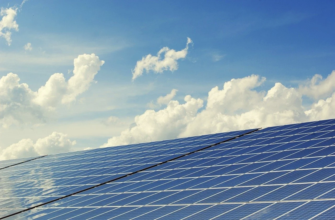
Human-engineered electromagnetism is not natural electromagnetism. Human-engineered electricity is either made from:

  1. Alkaline and lithium-ion batteries or other batteries use chemical reactions to generate and store DC electricity.

  2. AC (Alternating Current) uses rotating magnets and transformers to convert natural energy into electricity with a sinusoidal waveform at 50-60 cycles per second.

  3. Human-engineered DC (Direct Current) electricity is produced using rectifiers consisting of looped circuit alternating diodes switching on and off, and often adding resistors, a transformer/inductors, and capacitors to smoothen out the AC sine wave to form a pulsed DC at 120 Hertz.

  4. EMF emissions are from electrical equipment such as wifi routers, cellphones, cellphone tower transmissions, power lines, transformers, unshielded home wiring, electrical wiring errors, power tools, wireless surveillance systems, baby monitors, Bluetooth devices, and so much more.

The number of persons with EMF Sensitivity is estimated to comprise 3-5% of the population. The numbers could be much higher due to the growing awareness of EMF health effects and the regular addition of new wireless technologies. I want to add the perversely high percentage of poorly grounded homes and the high number of homes with electrical wiring errors made by unlicensed and poorly trained electricians.

Those who claim to be sensitive often begin feeling this energy in their early to mid-forties. (Although lately, we're encountering an increasing number of callers in their thirties and even twenties. In addition, many children with Downe syndrome or those on the spectrum present EMF sensitivity.

Most with EHS can relate to a time in their lives when they were exposed to specific electromagnetic fields for long periods. Examples are: sitting hours at their desk with the wifi next to them, sleeping near their electrical panel, welding for a living, using power tools for a living, driving a patrol car for many years, living under a power line, etc.

The realization that one is sensitive can be perplexing, daunting, or even terrifying. EHS can suddenly seem to happen in one day. Bam! You suddenly feel everything that produces electromagnetism. And then, the awareness that RF transmitters are everywhere! In the subways, everyone has a cellphone; smart meters are in your building, Bluetooth devices are in your home; electromagnetic radiation is ubiquitous!

Typical EHS symptoms include feeling an uncomfortable pressure in the cerebral cortex/occipital lobe areas, deep pain or pressure in the neck area or upper spine, chronic insomnia, brain fog, concentration issues, short-term memory lapses, or going suddenly blank in the middle of doing something, occasional vertigo, loud ringing in the ears, low-frequency rumbling sounds, unexplainable rashes or a burning or heating sensation in the skin, tingling sensations in the legs and arms, sharp headaches, sudden pain in an eye, intermittent irritability for no apparent reason, mood swings, irrational relationship-sabotage or self-sabotage, teeth grinding or clenching during sleep, and more. Every month, I hear of a new symptom.

* Again, if you experience any of these symptoms, I am legally obligated to recommend seeing your doctor.

Before continuing, I have to make one significant point: Everyone is adversely affected by EMF to one degree or another. Anyone who does not realize this or believes that their exposure to electromagnetic radiation is not a potential concern is ignorant of the peer-reviewed science. In addition, some professionals, including doctors, understand the health effects of electromagnetic radiation and why it can cause health problems. However, most realize this understanding requires a cross-discipline knowledge of physics and biology, Quantum Biology or Molecular Biophysics, which most doctors do not learn in medical school. 

After all, what is a chemical reaction? In essence, it is bonds created or broken by the sharing or releasing of electrons. In other words, a chemical reaction is an electromagnetic reaction.

From the vantage of all certified EMRS, an increasing number of people suffer from uncomfortable physical symptoms and illnesses due to electromagnetic radiation. We have each tested many homes of those claiming to have EMF Sensitivity. These clients felt the most discomfort when the EMF levels were at their highest in their homes. Most clients with EHS have consistently identified the areas in their homes with the strongest fields. For those who have proven to be truly sensitive, I encourage them to trust what they are feeling. We all need to do this; trust what we feel, but verify with accurate testing.

As already indicated, I know that most studies claiming the "data" prove that EMF Sensitivity appears to be “psychosomatic and idiopathic.” Yes, anything is possible regarding the tricks the mind can play. But what explains when someone gets a sharp pain without knowing that an active cellular antenna was nearby? What defines the consistency between the areas in their homes where they feel the worse, and the measured levels corroborate what they are feeling? We need to consider the possibilities.

Fortunately, I am well-versed in the scientific method and have reviewed every single one of these "studies" I could find which claimed to debunk EHS. What did I uncover?

I have found that each of these studies had at least one significant error or flaw involving either the set-up, measuring protocols, assumptions, data collection, or data analysis. To add, any person who has studied statistics also knows that a clever person can create a "study" to prove or disprove just about anything! Replicability is essential for verifying scientific conclusiveness. Without a third party replicating any of these debunking studies, anyone should not take their conclusions seriously.

All pain can be said to “be in the head.” Our brains receive signals from traumatized cells, irritated nerves and then register these sensations as pain.

Let's look at two studies.

When someone says that they felt pressure from applied electrostimulation and then 20 seconds later did not, it does not prove that this person was making their sensitivity up after being exposed the first time. And, for a scientist to draw this conclusion only provides us with information that they 1. do not understand the nature of EHS at all and 2. do not have the necessary talent, training, motivation, or discipline to conduct an open-minded experiment.

If nerves within the surrounding fine tissue containing trace amounts of metals, such as; copper, iron, silver, and others, are irritated, that fine tissue becomes inflamed or swollen, to some degree, in reaction to the irritation. As a result, these nerves may not differentiate a second exposure occurring within a short time interval from the first exposure. In addition, the slow healing time of swollen tissue will ipso facto cause the subject to lose the ability to differentiate consequential exposures.

Another “debunking study” shows that an EHS subject was "proven" to be duped by a placebo exposure to electromagnetism while sitting near the testing machine that was electrically floating, emitting a strong proximal electric field. The subject's feet were also close to the wall that may have had unshielded wiring, and overhead was an old-style magnetic ballast fluorescent light undoubtedly emitting a magnetic field, causing harmonic transients coupled onto the electric fields of the testing device itself. Who knows what the ambient EMR was in the room? Here was a "conclusive scientific experiment" that only proved the scientists' shortcomings.

What about studies from "third-party independent labs." So many of us can be gullible regarding the tricks of "science," either innocent or manipulative, that both science and the medical industry can play. We need to ask, "Who funded the study? Was this a shell company funding this study? Did the funder or the scientist have a bias or personal agenda? How was the data compiled and interpreted?" And then there's the whole concept of using relative versus absolute result ratios, which can skew any experiment's interpretation. 

Too many studies and their conclusions are unreliable and dishonest. This is why I do not “trust the science.” This is why I have to test myself. (5G is a good example. The present reality of 5G is not even close to what the TV commercials tell us that it is. Most likely, the sales and marketing managers do not even understand the details of the technology of 5G.)

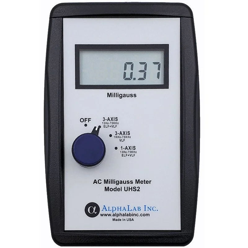
If you walk into a room and feel a strong EMF, measure it or have an Electromagnetic Radiation Specialist (EMRS) measure it for you. Everyone should own an AC gaussmeter and an RF meter. Amateur meters will tell you if the levels are going up or down. That is all you need to know in many instances. A certified EMRS can help you with solutions.

From what we EMRS have collectively observed, there appear to be consistencies between chemical toxicity sensitivity, Lyme disease, and EMF toxicity sensitivity. According to Dr. Martin Pall, Ph.D., one significant result of exposure to EMF is interference with calcium ion (Ca2+) motility and signaling in the body. This interference has a direct effect on neurology and autoimmune function. Thus, chemical and EMF sensitivity appears to be natural results of becoming over-exposed to particular environmental stressors or toxins. 

The human body is capable of sensing the lowest levels of electromagnetism. Dr. Robert O. Becker (The Body Electric) writes that the human body is sensitive to direct electrical stimulation down to nearly 100 nano-amperes. A nano-amp is a billionth of an amp or 0.000000001 amps. Today, Mount Sinai Hospital uses electrical stimulation, just a few hundred nano-amps of DC, to accelerate bone cell regeneration. Like many things, a little can be good, and a lot, not so good.

Our skin-voltage monitor shows our clients that the skin will react to electromagnetic fields with a strength as low as a thousandth of a volt, a millivolt. During an epidermal voltage measurement, one never consciously feels anything on their skin, yet the skin responds immediately to the slightest change in the electric field. Thus, the epidermis is highly sensitive to electromagnetism, whether we consciously feel it or not.

To further show how sensitive we are to the smallest amounts of microsimulation from electromagnetism, Guy Doron and Michael Brecht published a work in 2015 titled "What Single-Cell Stimulation Has Told Us About Neural Coding." 

In this report, they state, "The later development of intracortical microstimulation (ICMS), a technique in which trains of short (100–200 ms) constant electrical pulses of small current intensities (1–100mA) are delivered extracellularly via a microelectrode at rates of tens to hundreds of Hertz, enabled a more reliable activation of localized populations of neurons and directly influenced sensory perception, movement, and cognition."

Of course, none of us can consciously sense levels as low as a few hundred nano-amps. Still, there is mounting scientific evidence that conscious sensitivity to higher levels is a natural result of one having higher levels of trace metals or even naturally occurring biogenic magnetite in their tissues. The latter resulted from a study by Caltech's Joseph Kirschvink in 1992. 

http://www.roaringlionpublishing.com/tony_uploads/Magnetite_Biomineralization_in_the_Human_Brain.pdf

Here, Kirschvink reveals that we all have ferromagnetic magnetite (Fe3O4) in our brain tissue and throughout our bodies. Iron is not only conductive, but iron is also is susceptible to magnetic fields.

In 1975, Allen Frey demonstrated that continuous exposure to microwaves at power densities as low as 30 µW/cm2 (30,000 µW/m2) could weaken fine membranes such as the blood-brain barrier (BBB). A permeable BBB will allow larger-sized trace-heavy metals, such as mercury, cadmium, aluminum, lead, antimony, and others, to penetrate the BBB. 

Eberhard et al. (2008) report that two-hour exposures to cell phone GSM microwave RF resulted in albumin leakage across the blood-brain barrier (BBB) and neuron damage. Neuronal albumin uptake was significantly correlated with the occurrence of damaged neurons when measured at 28 days post-exposure. The lowest exposure level was 0.12 mW/kg (0.00012 W/kg) for two hours. The highest exposure level was 120 mW/kg (0.12 W/kg). The weakest exposure level showed the most significant effect in opening the BBB and neuron damage and death. https://www.elexana.com/news/2017/12/22/cell-phone-study-drastically-lowers-safety-thresholds

Are our brains also electromagnetic sensors? In 2016, Joseph Kirschvink proved that we use biogenic magnetite to sense polarity changes in the Earth's magnetic fields. This sense helps our brain's awareness of daytime short waves shift to nighttime's much longer waves, signaling the pineal gland to release melatonin.

Yes. Science is speaking. We are all sensitive to electromagnetic fields. This phenomenon is why it is so critical that we mitigate the strong fields created within our homes and workplaces. 

Sometimes, those with EHS feel like they are "trapped in this modern technological world."

There is hope. Removing trace metals from the blood takes time, but clients have done it. Unfortunately, discharging trace metals from the brain area is more challenging once they pass the BBB. Yet, I believe it is possible to release these toxins. For that matter, so does the University of Kentucky's Dr. Boyd Haley, who has a chelating agent in the final testing stage for FDA approval.

Another theory for the cause of EHS symptoms is that some are deuterium toxic and can't release this heavy form of hydrogen. It is found everywhere in the universe. D2O is the heavy water we use to cool nuclear reactors. High-fat diets seem to help the body release deuterium. There is much we don't know about this area of research.

Some medical practitioners, such as Dr. Jerry Tennant, believe that emotional trauma causes DC magnetic fields to become stored in the limbic system. Some medical practitioners believe that healing therapies can help reduce limbic system magnetic fields to reduce sensitivity to EMF.

In conclusion, some folks have not only found relief from the intensity of EHS but have risen above the existential angst of feeling trapped without an escape from our modern world's ubiquitous human-engineered electromagnetic radiation. So, please, do not despair. Reach out to your local EMRS for a home consultation. If you do not have a local EMRS, please call Elexana for virtual testing via the zoom platform. Take control of your immediate environment as best you can.

What is the Difference Between Residential EMF/EMR Testing and Electrical Services Provided by an Electrician?

All Electrical Services are provided by electricians licensed in the county where you reside, and EMF/EMR Testing and Mitigation Consulting Services are provided by nationally certified Building Biology® Institute of America Professional Electromagnetic Radiation Specialists (EMRS.) If you hire anyone else to test the electromagnetic fields in your home other than an EMRS or Michael Neuert, of the EMF Center in California, then best of luck.

  • An EMRS conducts a series or panel of non-invasive testing, performs a certified analysis of the data, then presents an informed consultation to the client including the next recommended steps to mitigate any actionable findings. Some of these solutions may then involve an electrician.

  • A licensed electrician will then do the electrical work required to correct any electrical errors or necessary upgrades uncovered by the EMRS uncovered by non-invasive EMF/EMR testing and visual inspections. (Non-invasive means that we do not remove electrical panel covers, junction box covers, or outlet receptacle cover plates.)

Persons engaged in either of these professions undergo extensive training, coursework, and must successfully pass written exams.

  • It takes someone about 4-5 years to become a licensed electrician.

  • It takes 3-4 years to become a certified EMRS. Both electricians and EMRS should carry General Liability Insurance to enter your property and you the consumer have a right to request to see visual proof of this insurance.

Just like any other profession, there are various levels of talent and expertise within a certain range of each and every EMRS. Some are excellent and some are just getting started on their own. But, like all professions, at least you know that the baseline is professional competence. At Elexana LLC, we would like to think that we have some of the best in the field.

EMF/EMR Testing and Mitigation Consulting Services should only be offered by a trained and certified EMRS or someone under their supervision. 

An EMRS receives extensive training from EMRS-electrical engineers, EMRS-electricians, and other experienced certified EMRS at the Building Biology® Institute of America. She or he must pass several exams and a final project before receiving an accredited certification. 

There are no services that an EMRS provides homeowners that have not been taught at the BBI and sufficiently learned. Punctuated is the distinction between EMF/EMR testing and mitigation consulting services and electrical services to every student.

In short, an EMRS surveys electromagnetic fields seeking out sources for EMR emissions and consults with you, your engineers, electricians, and contractors when there is an electromagnetic interference issue requiring a specific mitigation plan, operation, or application. 

It is your locally licensed electrician who will do the actual electrical work to implement any necessary corrections and install any electrical filters, switches, ground rods, etc. Unless an EMRS is also a licensed electrician, an EMRS does not perform electrical services. 

From our experience, most electricians fail to identify and correct wiring errors if left on their own without guidance or direction. One can wire a renovation or new chandelier where the lights will turn on, but in the process may also violate several NEC requirements that produce harmful magnetic field emissions and pose a potential fire risk. Many electricians mistakenly think that the fix for a wiring error is in grounding and bonding circuits properly. Hiring an EMRS, in this circumstance, to work in concert with your electrician is often helpful. The EMRS can guide how to identify the circuits where there are parallel returns. This training is just one learned protocol that separates the professional EMRS from the typical New York TriState EMF expert or inspector.

Another non-invasive test an EMRS conducts is measuring stray current and voltage on your water service, coaxial cables, and gas lines. Home inspectors and electricians do not check these utilities for stray current, which can cause potential health and safety issues.

A third test that an EMRS could conduct that is non-invasive that a home inspector for electrician does not provide to measure the impedance on the system ground. If there is a ground loop or exceedingly high impedance, this will cause the electric fields inside the home to be stronger than if the system ground were functioning with a proper impedance. Shunting the electric fields to the earth ground is essential. Furthermore, a flawed system ground poses a potential shock and fire hazard. 

Most electricians are not aware that many common wiring errors can produce elevated magnetic field radiation and pose a fire hazard. After all, according to the NFPA, 48% of all home fires are electrical.

Induced magnetic fields from specific wiring errors can adversely affect sensitive electronic equipment and cause ill-health after prolonged exposure. If relatively low AC magnetic fields comparable to the US standards, which are virtually non-existent, did not cause interference, all AC magnetic shielding companies would be out of work. It would take me much less time to consult on the best placement for Magnetic Resonance Imagers (MRI), Ultrasound Imagers, Electron Microscopes and Scanners, and other scientific and medical equipment. Determining pacemaker compatibility would be a breeze.

A fourth non-invasive test that an EMRS conducts that no electrician or home inspector offers is to test the levels of harmonic line noise and airborne interference coupled to indoor electric fields, often called "dirty electricity." There are several techniques to assess these frequencies, but again, all tests are non-invasive. 

A fifth non-invasive test that an EMRS conducts that an electrician does not is a radio frequency scan. Strong radiofrequency radiation levels can cause electronics to malfunction and ill-health with prolonged exposure, according to the scientists of the Bio-initiative, Physicians for Safer Technology, and the scientists of The Environmental Health Trust.

Finally, an EMRS is a consultant who can offer their educated and experienced opinion on best practices for EMF/EMR/EMI mitigation. This knowledge and expertise are beyond the training scope that a home inspector or an electrician receives. The electrician or licensed electrical contractor works to mitigate the non-ionic radiation produced by wiring errors, unshielded electrical cables, poorly grounded homes, and installing all electrical equipment, EMR remediation equipment, etc.

So, yes, although all tests that an EMRS conducts are non-invasive, they do require training and certification. Unfortunately, there is no license issued in any country or court for EMF/EMR testing. We certainly wish there were. Requiring a license would ensure that the consumer receives a baseline of competency.

Earthing, Grounding, and Bonding

earthing-elexana-llcjpeg

Misunderstood and misinterpreted concepts circulate the world of EMF remediation consulting, especially those involving earthing, grounding, and bonding. Hopefully, this article will help you improve your knowledge and understanding of these terms.

Are you connected to the electrical system or the Earth?

Are you connected to the electrical system or the Earth?

To begin, let's define the term electrical conductor. A conductor is any material that allows electric charge to move through it with relatively low resistance. The human body is a moderate conductor due to ionic fluids (saline), not metal conduction. Current can flow both across the skin and through the body, depending on frequency and contact conditions. When a ground rod (also called a grounding electrode) or a human being connects directly to Earth, we call this Earthing.

(When you lie on a “grounding” mat plugged into your wall outlet ground conductor, are you connected to the electrical system or to Earth? — Answer: To your electrical system.)

Image: Lightbulb man.

The frost line varies widely by region (often 12–60+ inches in the U.S.). Everything above this depth may freeze in winter in cold climates.

This top layer of Earth's skin is where most stray voltage and current traverse, especially when the soil is moist. Stray current tends to follow paths of lowest impedance through soil, which may include moist near-surface layers, but can also extend deeper depending on soil stratification. This energy comes from nearby electrical power lines, substations, and underground cabling.

During geomagnetic storms, ionospheric currents can induce quasi-DC currents in long transmission lines (GICs), which may contribute to transformer saturation and abnormal system behavior on the power grid. Harmonic distortion in buildings, however, is typically driven by non-linear electronic loads and utility-side power quality conditions.

RF energy from modern communications can interfere with some measurement instruments if not properly filtered, which is why professional soil resistivity testing uses standardized methods and appropriate filtering. These transients must be compensated for when conducting soil resistivity tests using low-pass filters.

Low temperatures and low moisture content increase soil resistivity. Soil impedance can also be frequency-dependent, but standard grounding measurements are typically referenced to power-frequency behavior. The NFPA 70E® requires an impedance of 25 ohms or less for a grounding electrode to function correctly, except when sensitive electronics are involved, where 5 ohms is required. Power stations will require 0.5 ohms (IEEE 1.9.5) (2025)

Earth is not the intended ground-fault current return path for clearing breakers.

The NEC includes a commonly cited 25-ohm resistance-to-earth value for a single rod electrode, and if that value is not achieved, an additional electrode is required (NEC 250.53(A)(2)) (2025). Many facilities with sensitive electronics may be designed for lower values. Still, those targets depend on system requirements and are governed by specialized standards such as IEEE and telecommunications grounding practices.

(NEC 250.54 (A) (2025) states: "A single electrode consisting of a rod, pipe, or plate that does not have a resistance to ground of 25 ohms or less shall be augmented by one additional electrode of any type specified in section NEC 250.52 (A) (4) - (a)(8). (2025)" To achieve this target of 25 ohms or less, we must drive an eight-foot ground rod beyond this thirty inches until the rod's top is either level or just below the surface (NEC 250.53 (G)) (2025). 

(Depending on the soil resistivity, you may need more than one eight-foot ground rod inserted to a deeper calculated depth than eight feet, or alternative methods may be applied using ground rings, ground plates, or ground trenches. Each of these electrodes must be a minimum depth of 30 inches (NEC 250.53 (F)(G)(H))(2025).

A low-impedance equipment grounding and bonding path is required to clear ground faults by returning fault current to the source. The grounding electrode system primarily stabilizes the system to earth and helps dissipate lightning/surge energy. To protect our buildings from high-voltage lightning strikes, line surges, or unintentional contact with high-voltage lines (NEC 250.4 (A)(1)) (2025), a low-impedance grounding electrode is required to provide an effective ground-fault path to Earth. NEC 250.66(A)(2025) requires a 6 AWG copper wire or a 4 AWG aluminum wire for the grounding electrode conductor, fastened with a copper or galvanized clamp, to connect the ground rod to the ground/neutral busbar inside the Mains electrical panel. (Some panels have separate ground and neutral busbars connected via a bonding screw (often painted green) or a bonding strap.) The neutral return wires (usually gray or white) from every branch circuit in your building and all ground conductors (green wire) from every wall outlet receptacle eventually connect to the Mains neutral busbar. The neutral busbar's return conductor connects to your power company's transformer through your electrical service entry. The transformer is the drum on the telephone pole if you have overhead distribution lines, or the metal cabinet near your front lawn if you have underground distribution lines.

To further protect your building from a catastrophic lightning strike, NEC 250.104 (2025) requires that all water and gas pipes be bonded. Bonding means connecting all metal piping and structural steel (NEC 250.52 (A)(2))(2025) and linking them back to the grounding electrode. All raceways (NEC 250.96)(2025) and metal cabinets, such as your refrigerator, stove, washer and dryer, toaster oven, etc., must be grounded/bonded via the ground conductor pins on their plugs to the wall outlet ground socket (NEC 250.114.) (Note: This connection also protects you from a shock hazard in case of a short by initiating the GFCI, Ground Fault Circuit Interrupter, or your circuit breaker to flip.) The term "grounding" means connecting your appliances and devices to the Equipment Ground Conductor, EGC, your Mains panel neutral busbar, and then out to the grounding electrode. 

Here is a simplification of the NEC’s definitions, which I concur:

  • Grounding = connecting to earth

  • Bonding = connecting metallic parts to ensure continuity and a fault-current path

  • Equipment grounding = connecting equipment enclosures to the grounding conductor system.

The Earth does not provide ample protection from a lightning strike, so the final protection is the overload ground conductor connecting your neutral busbar to your water service pipe in your basement near where it enters your building. The excess voltage will travel from your water pipe, "leap" over your water meter via a jumper, and continue onto the municipal water supply, absorbing all extra voltage. Bonding the metal water piping system helps equalize potential and reduce shock hazards during faults or lightning events. It is not intended as a primary lightning dissipation system.

Many folks falsely believe that the grounding conductor in their home or office is some pristine connection to Earth. This idea could not be further from reality. Even with loads off, grounding conductors can exhibit induced voltages and may carry stray currents if bonding errors or utility neutral return issues exist. Depending on radio frequency interference and the condition of your local transformer, you will have a wide bandwidth of harmonics (dirty electricity) on this conductor and your neutral conductor. 

Some clients who wish to "ground" themselves from their office or home have asked if they could drive a separate, independent ground rod into the Earth and not connect it to the Mains panel. We can't endorse this practice because NEC 250.50 requires bonding for all grounding electrodes. Remember, this code is to protect you. Further, stray voltage and current traveling along the ground's surface may corrupt your temporary ground rod without adequately testing soil resistivity.

Earthing can provide real health benefits. Not only will earthing shunt unwanted voltage from your epidermis, but the Earth also contains negative ions, which can have a restorative and therapeutic effect. Natural environments often have higher air-ion concentrations (for example, near moving water and after thunderstorms). Some studies have explored whether air ions influence mood and well-being, but the research is mixed and not definitive. Negative ions exist in ocean water, flowing streams, and clean air, especially after thunderstorms. Negative ions also flow from sunlight and the Earth. Earth, of course, unless human-engineered stray voltage or current travels along its surface. 

If you live in a city or suburb, you are most likely not earthing when you walk barefoot in your backyard. You would certainly not be earthing if you walked down the sidewalks of most New York City streets. In urban environments, bare feet on damp concrete can sometimes expose a person to stray voltage under certain fault conditions. Concrete’s conductivity varies with moisture and reinforcement. In urban environments, bare feet on damp concrete can sometimes expose a person to stray voltage under certain fault conditions. Concrete’s conductivity varies with moisture and reinforcement. This activity could pose a potential shock hazard if a nearby utility is shorted.

If you want to know if you are genuinely earthing, verify the soil resistivity. (Note: Although earthing will bring your relative potential to zero millivolts (skin-body voltage/epidermal voltage), all energies will still couple to the epidermis if you are within a power-dense electromagnetic field. In other words, earthing shunts voltage but does not block or prevent you from exposure to electromagnetic radiation.)

In summary, earthing occurs when we directly connect to Earth, grounding when we connect a conductor to the electrical system ground/neutral busbar, and bonding when we connect metal casings and pipes to the system ground/neutral busbar. 

We all need to experience Nature as often as possible, get plenty of sunlight and fresh air, and move our bodies throughout the day. Swimming in the ocean and walking on a beach provide earthing benefits. In contrast, grounding yourself to your electrical system is not earthing. I encourage you not to be so naive about every alternative therapy and remedial device, no matter how many positive reviews and endorsements it has.

earthing-beach-elexana-llc.jpeg

*If the grounding electrode is encased in concrete, then a 4 AWG copper wire is required (NEC 250.66 (B))

©Copyright 2026. All rights are reserved by ELEXANA LLC.