Applications of ALARA EMF-EMI Design in Critical Environments and Wellness-Centered Architecture


As our built environments become increasingly saturated with electromagnetic fields—from power systems, wireless networks, and digital technologies—the need for electromagnetic risk-conscious design is more relevant than ever. The ALARA principleAs Low As Reasonably Achievable—developed initially in radiation safety, is now finding essential applications in EMF-EMI architectural consulting and electrical design.

At Elexana LLC, we integrate ALARA EMF-EMI Design into various real-world projects, each with distinct exposure concerns and design priorities. The following are five key environments where this approach provides critical protection, system reliability, and long-term value.

1. Homes for EMF-Sensitive Individuals or Families with Children

For individuals diagnosed with Electrohypersensitivity (EHS) or parents seeking electromagnetic safety for young children, ALARA-based residential design offers practical relief and peace of mind.

Applications Include:

  • Remediate bedrooms to ultra-low magnetic field levels (<0.1–0.2 milligauss)

  • Elimination of in-wall Wi-Fi routers, Bluetooth devices, or RF-emitting thermostats

  • Radial wiring layouts to avoid current loops and ELF field buildup

  • Remote shutoff switches to eliminate AC electric fields during sleep

  • Use of MC-shielded cables and fiber-optic networking

Benefits:

  • Reduced risk of sleep disruption, behavioral disturbances, or long-term biological effects

  • Validated environment for EMF-sensitive residents

  • Better energy hygiene in restorative living spaces

2. Hospitals, MRI Facilities, or Operating Rooms

Hospitals present some of the most complex electromagnetic environments. They house life-sustaining medical equipment alongside patient care areas that must be protected from interference.

Applications Include:

  • RF shielding of operating rooms or surgical suites to ensure EMI-free performance of monitoring equipment

  • Isolation of high-current MRI and CT scan rooms from patient recovery zones

  • EMF exposure reduction around neonatal ICUs or maternity wards

  • Coordination with IEC 60601 and FCC EMI limits for medical device operation

Benefits:

  • Reduces false readings or device malfunctions

  • Enhances safety for patients with pacemakers or implants

  • Prevents litigation due to electromagnetic system failures

3. Laboratories and Clean Rooms with EMI-Sensitive Instrumentation

High-precision research environments, especially those using electron microscopes, nano-scale sensors, or quantum computing hardware, are acutely sensitive to radiated and conducted EMI.

Applications Include:

  • RF shielding of lab spaces and clean rooms to isolate sensitive measurements

  • Installation of power-line EMI filters and voltage isolation transformers

  • Use of magnetically shielded walls and flooring

  • Identification and mitigation of stray EMI from adjacent HVAC, VFDs, and digital lighting

Benefits:

  • Increased measurement accuracy and reproducibility

  • Reduced signal drift and lab instrument recalibration time

  • Validation of high-performance clean room integrity

4. Recording Studios, Financial Trading Floors, and Data Centers

Some economically sensitive environments rely on uninterrupted electronic performance and minimal noise distortion. Even subtle EMI or EMF coupling can result in signal contamination, trading delays, or system-wide outages.

Applications Include:

  • EMI/RFI shielding of recording studios to protect microphone signals from digital noise

  • Use of shielded data cabling and power line filters in financial terminals and trading stations

  • Field minimization in data centers to prevent server resets, storage corruption, or grounding faults

Benefits:

  • Preserves the integrity of audio, data, and communications

  • Supports mission-critical uptime and cyber-physical stability

  • Prevents interference between analog and digital subsystems

5. Luxury Custom Residences, Holistic Retreats, and Health-Centric Developments

Affluent homeowners and wellness-focused developers increasingly demand low-EMF, low-noise, and biologically aligned environments for comfort, long-term health, and market value.

Applications Include:

  • Whole-home RF mitigation strategies

  • EMF-free zones for yoga, meditation, or recovery therapy rooms

  • Use of natural materials and non-wireless infrastructure in green building certification

  • Embedded field measurement validation in pre-sale marketing packages

Benefits:

  • Enhances well-being for health-conscious residents and EHS clients

  • Adds value through future-proofing and environmental certifications

  • Aligns with sustainability, biophilia, and holistic architecture principles

Conclusion

ALARA EMF-EMI Design is not just a precautionary concept—it’s a comprehensive design practice rooted in physics, health science, and architectural engineering. It delivers measurable protection, enhanced reliability, and occupant trust, whether used in homes, hospitals, labs, or data-driven environments.

At Elexana LLC, we help clients design with science-backed awareness and electromagnetic transparency, ensuring that today's buildings are prepared for tomorrow's demands and sensitivities.

© Copyright 2025. All Rights are Reserved.

Why a Multimeter is Not Used for Ground Testing or to Identify Ground Loops

Recently, I reviewed a report as a third-party consultant for a client who needed a second opinion. In the report, the engineer used a Fluke 323 Clamp Multimeter to measure the impedance on a building’s ground conductor. Because this meter can measure impedance, many get tricked into thinking it can measure a ground system's impedance. Although this tool is excellent and used by many electricians, it was incorrect for this job.

Here is an outline explaining why this is the wrong tool and some tool suggestions for the next time.

This is one of several correct tools, an AEMC 6417 Ground Tester, for measuring a system ground that Elexana utilizes.

Why a Multimeter Is Inadequate for Ground Impedance and Ground Loop Detection

1. Measurement Frequency Limitation

  • Multimeters measure impedance using DC or very low-frequency AC (in the case of True RMS meters).

  • Ground impedance relevant to safety and EMI performance must be evaluated at 50/60 Hz and higher frequencies (e.g., several kHz or even MHz for EMI).

  • Ground loops can involve complex impedance behavior due to parasitic inductance and capacitance, which a multimeter cannot resolve.

2. Insufficient Current Injection

  • Proper ground impedance testing requires injecting a high current (25 A or more) into the earth electrode and measuring voltage drop (per standards like IEEE 81 or NEC 250).

  • A multimeter provides microamp to milliamp current, which is insufficient to develop a measurable voltage drop across low-impedance ground systems (often < 1 ohm).

3. Cannot Isolate Parallel Paths

  • The grounding system in a facility has many parallel paths (building steel, water pipes, cable trays, etc.).

  • A multimeter cannot distinguish between these paths or model their inductive coupling, meaning it cannot identify unintended loop currents or impedance differentials.

4. No Differential or Noise Detection Capability

  • Ground loops often arise due to minute voltage differences (millivolt to volt scale) between ground reference points under load or EMI conditions.

  • Multimeters cannot effectively isolate AC noise, ripple, or transient voltages across these ground paths, especially in the presence of switching power supplies, VFDs, or large equipment.

Best Tools for Testing Ground Impedance and Ground Loops

A. Ground Electrode Impedance Testing (Low-Frequency, Safety-Oriented)

  1. Clamp-On Ground Resistance Testers

    • Example: Fluke 1630-2 FC or AEMC 6416

    • Measure ground loop impedance without disconnecting the ground rod.

    • Use current injection and voltage sensing coils to compute ground impedance in situ.

    • Best for bonded systems and electrical safety evaluations.

  2. 3-Point or 4-Point Fall-of-Potential Test Kits

    • Example: Megger DET4TC2 or AEMC 4620

    • Used for soil electrode testing per IEEE 81 and IEC 60364, especially in unbonded grounding systems.

    • Injects known current into the earth and measures potential drop at various distances.

B. Ground Loop and Noise Identification (AC Noise, EMI, Safety)

  1. Oscilloscope with Differential Probes

    • Use Case: Detect high-frequency or transient ground loop voltages, such as from VFDs or data systems.

    • Enables visualization of non-sinusoidal voltages and high-frequency disturbances.

    • Use a low-voltage differential probe (e.g., Tektronix TDP0500 or Pico TA043).

  2. AC Leakage Current Clamp Meter (High Sensitivity)

    • Example: Fluke 369 FC (sensitivity down to 60 µA)

    • Measures unintended ground currents, leakage, or circulating currents.

    • Helps identify ground loops by comparing current paths across different grounding bonds.

  3. Power Quality Analyzer or EMI Analyzer

    • Example: Fluke 435-II or Narda EHP-50C

    • Measures harmonics, transients, and noise currents on grounding conductors.

    • Useful in industrial or EMI-sensitive environments.

  4. Signal Injectors and Ground Loop Testers

    • Inject a known AC signal on a ground conductor and detect unexpected paths or voltage differentials.

    • Some EMC consulting tools include signal tracing with phase tracking to map unintended loop routes.

Summary

  • A multimeter is a scalar, low-energy, low-frequency tool that cannot measure complex impedance, detect noise voltages, or model multi-path grounding systems.

  • Use clamp-on ground testers and 3/4-point test kits for impedance and differential probes, AC leakage clamps, and EMI analyzers for ground loops and interference.

©2025 All Rights are Reserved.

Is There a Conflict of Interest to Own an Accredited EMI-EMC Test Lab and Be an EMI-EMC Consultant?

Ah, let’s break this down. So why would it be a conflict of Interest to have an accredited EMI-EMC Test Lab and an EMI-EMC consulting service? I have grappled with this question until recently because I am an EMI/EMC Consultant. However, I also wanted to set up an accredited EMC test lab because I already know how to run these tests and have much of the same equipment these labs use.

Funny, how God will often bring people into our lives who intentionally or unintentionally show us the answers to the questions we struggle with. Hearing the story from a new prospective client who had lost their patience with repeated compliance test failures down in North Carolina, and his frustration on the wasted time and money he spent on the lab tech’s trying to provide a “quick-fix” so his unit would pass compliance made it so very clear of the dubious conflict that supposedly independent testing and “fixing” the problem posed.

This is when the product designer needs to call an external independent consultant, an EMI-EMC Consultant like ELEXANA, and this is why we are no longer going to strive towards converting our Pre-Compliance Test Lab or our Mobile EMI-EMC Test Lab into accredited test labs. Running pre-compliance tests to check if the design modifications we are working on will pass is way less expensive than going to an EMC Test House to do this, sometimes, a back-and-forth process.

EMI Pre-Compliance testing software will typically present the Compliance Standard’s Pass-Fail threshold lines and a dotted line 6 dBµV (decibels microvolts) below the threshold Pass-Fail line of demarcation. Pre-Compliance design aims to have all frequency amplitudes below the dotted line. This way, there is more confidence in not wasting more funds at an EMC Test House.

Usually, the EMI Consultant is hired for a certain number of days to work with you and your team at your location. The number of days is determined by the time the developers have already struggled, the complexity of the DUT (Device Under Test) or EUT (Equipment Under Test), and the number of failed test frequencies.

Here is a more detailed outline of why using an accredited compliance lab would be entering into a conflict of interest in identifying why a product cannot pass compliance and making efforts to remedy this problem.

Here is one of our TEM-cells (Transverse Electromagnetic Cell), a test chamber, inside a Faraday Cage. You can see the DUT on the dielectric material. This TEM cell is connected to our EMI Receiver which contains the EMC Pre-Compliance software. This system for testing small products, PCBs, or power supplies, for radiated emissions is very accurate.

Why It Can Be a Conflict of Interest

1. Compliance labs are paid to test, not to fix

  • Accredited labs (e.g., for FCC, CE, MIL-STD) are typically certified to run standardized compliance tests and report pass/fail results.

  • Their role is verifying compliance, not independently advising or engineering product fixes.

  • If the same lab that certifies compliance also offers “for-hire” troubleshooting services, it creates an incentive to:

    • Prolong testing or problem identification to increase billable hours.

    • Blur the line between neutral assessment and commercial involvement in redesign.

2. Accreditation rules emphasize independence

  • Many standards bodies discourage or forbid accredited labs from acting as design consultants on the same product.

  • The lab’s value is in providing impartial verification — if they help solve the problem, they effectively become part of the design team, which can undermine the neutrality of the certification.

3. Potential for biased recommendations

  • A lab offering investigation services might advocate fixes or retesting that favor its process, tools, or interpretation rather than an optimal or independent engineering solution.

4. Liability and legal clarity

  • If a product fails compliance after passing through both the lab’s investigation and certification services, it raises difficult questions:

    • Was the lab objective in its assessment?

    • Did it miss or cover up issues to preserve the client relationship?

    • Who is liable for the failure?

How to Manage This:

  • Use separate teams or organizations:

    • Accredited labs should handle compliance testing only.

    • Independent EMC/EMI consultants should investigate, diagnose, and help fix the causes of failure.

  • Ensure clear contractual separation between testing and troubleshooting work.

  • Be cautious if a lab offers “help” beyond its accredited testing scope — ask about their independence and how they manage conflicts.

At ELEXANA we work for our clients, not for ourselves.

©2025 All Rights are Reserved.

What are the Differences Between an EMI Survey, an EMI Investigation, and an EMI Inspection?

This article is long overdue. Most companies that call on Elexana for help with equipment failure due to electromagnetic interference will often start the conversation with, “I never even heard of EMI!” In their situation, the OEM, the equipment manufacturer, told them, “It’s not our equipment; you need an EMI inspection, an EMI survey, or an EMI Investigation.”

Most prospective clients are new to this concept of EMI and consequently ask for the wrong service. To help prevent this mistake, we ask them to tell us what is happening and why they think they need our services.

This article will be in outline form to review the general differences, the skillsets, and the knowledge base requirements.


What is an EMI Survey?

Definition: An EMI survey is a broad assessment or scan of an environment (like a facility, site, or room) to measure the existing electromagnetic environment — essentially, to map out where electromagnetic fields (EMFs) or interference sources are present.

Purpose:

  1. Check background EMI/EMF levels.

  2. Verify compliance with environmental standards.

  3. Identify hotspots or areas at risk of interference.

  4. It is often done proactively as part of site qualification, especially in sensitive environments like hospitals, labs, or data centers.

Scope:

  1. Wide area or whole system.

  2. Focused on characterizing the environment, not necessarily finding the cause of a specific problem.

  3. May involve long-term monitoring or periodic checks.

Key Features of an EMI Survey

1. Detailed Measurement of Electromagnetic Fields.

  • Uses calibrated instruments (spectrum analyzers, EMI receivers, near-field probes, antennas, field strength meters) to quantify electromagnetic emissions across defined frequency ranges.

  • Captures both radiated and conducted emissions.

2. Baseline EMI Environment Assessment.

  • Maps out the existing electromagnetic environment in a site (facility, lab, data center, hospital, etc.).

  • Identifies background EMI sources (external: like nearby radio transmitters; internal: like industrial machinery or IT equipment).

3. Compliance Verification.

  • Compares measured emissions and susceptibility levels to relevant EMC standards (FCC Part 15, IEC 61000, MIL-STD-461, CISPR standards, etc.).

  • Ensures systems are within acceptable EMI limits.

4. Identification of Potential Risks.

  • Highlight equipment or locations vulnerable to EMI problems.

  • Identifies EMI “hot spots” where emissions may exceed thresholds or pose interference risks.

5. Comprehensive Site or System Coverage.

  • Includes multiple locations across a site (rooms, floors, equipment racks, shielded enclosures).

  • Often includes airborne (radiated) and line-bound (conducted) interference checks.

6. Use of Specialized Measurement Techniques.

  • Near-field vs. far-field probing.

  • Broadband vs. narrowband scans.

  • Time-domain or frequency-domain analysis.

7. Reporting and Documentation.

  • Provides detailed measurement data, spectral plots, field maps, and tables.

  • Includes a written summary of findings, risk assessment, and recommendations for mitigation (if needed).

8. Support for Further Investigation or Design Improvement.

  • Acts as the foundation for:

    • EMC design improvements.

    • Shielding or filtering upgrades.

    • Root-cause investigations are conducted if specific EMI problems are uncovered.

Where Are EMI Surveys Used?

  • Hospitals (to protect sensitive medical devices).

  • Data centers (to ensure reliable IT performance).

  • Manufacturing facilities (to safeguard automated systems and robotics).

  • Research labs (where precision measurements are EMI-sensitive).

  • Military or aerospace sites (where strict EMC standards apply).

  • Office or residential towers (especially near strong RF emitters).


What is an EMI Investigation?

Definition: An EMI investigation is a targeted diagnostic process triggered by a specific problem or suspected interference. It aims to identify, isolate, and resolve the root cause.

Purpose:

  1. Understand why a device or system is malfunctioning or failing EMC tests.

  2. Trace the specific interference source (which could be internal or external).

  3. Recommend solutions (shielding, grounding, filtering, redesign, etc.).

Scope:

  1. Narrowed to the system or components involved in the failure.

  2. Involves deeper, often more technical, analysis (including circuit-level reviews or near-field probing).

Definition of an EMI Inspection

An EMI inspection is a structured visual and procedural assessment that identifies, evaluates, and documents potential electromagnetic interference (EMI) risks in a facility, system, or device. It focuses on verifying physical and design compliance with best practices and standards for electromagnetic compatibility (EMC) without necessarily performing detailed field measurements or advanced diagnostics.

Purpose of an EMI Inspection

The primary purposes are Proactive Risk Identification and Detection of potential EMI issues (such as poor grounding, bad cable routing, or missing shielding) before they cause failures or noncompliance.
Compliance Verification—Ensure that installations, designs, and operational practices meet relevant EMI/EMC standards (such as FCC, IEC, or MIL-STD requirements).
Quality Assurance — Provide confidence to stakeholders (clients, regulators, or internal teams) that EMI risks have been evaluated and mitigated.
Preparation for Further Work — Determine if a detailed EMI survey or investigation is necessary.
Post-Mitigation or Commissioning Check — Confirm that corrective actions or new installations meet EMI performance expectations.

Scope of an EMI Inspection

The scope of an EMI inspection typically includes:

  • Visual Examination

  • Grounding and bonding integrity.

  • Cable routing and separation of power/signal lines.

  • Shielding effectiveness (enclosures, cables, connectors).

  • Equipment layout, especially proximity to known EMI sources.

  • Document and Design Review

    • Wiring diagrams, grounding plans, shielding designs.

    • EMC requirements are specified in design documents or contracts.

  • Basic Instrumentation Checks (if included)

    • Handheld or portable tools for spot-checking emissions or coupling.

    • No full-scale frequency scans or field mapping (which belong to EMI surveys).

  • Standards & Requirements Check

    • Assess alignment with applicable EMI/EMC standards (e.g., FCC Part 15, IEC 61000, MIL-STD-461, DO-160).

  • Reporting and Recommendations

    • Provide a formal report outlining findings, compliance status, and recommended actions if risks or gaps are identified.

What’s Not Typically Included?

  1. Full-spectrum EMI measurements across all bands.

  2. Detailed root-cause analysis of specific EMI failures.

  3. Laboratory-based compliance testing for certification.

  4. Deep signal integrity or high-frequency analysis.

These fall under EMI surveys, investigations, or certification testing, not basic inspections.

Key Features of an EMI Inspection

Visual and Physical Assessment

  • Inspect physical installations for EMI risks:

    • Grounding and bonding connections.

    • Cable routing and separation (signal vs. power).

    • Shielding integrity (cables, enclosures, connectors).

    • Equipment layout relative to known EMI sources.

Documentation and Design Review

  1. Examine wiring diagrams, grounding layouts, and shielding designs.

  2. Check that the installation matches the design specifications and follows EMC best practices.

  3. Review compliance with applicable standards or client requirements.

Compliance Check (Without Full Measurements)

  1. Verify that systems and installations meet procedural and physical requirements for EMI control, even if no detailed field measurements are taken.

  2. Look for known noncompliance risks (e.g., missing ferrites, improper shield termination, unbonded panels).

Spot Checks (If Needed)

  1. Perform basic EMI spot measurements at suspect locations using handheld or portable meters.

  2. This is limited and does not replace an EMI survey's full spectral or quantitative analysis.

Reporting and Recommendations

  • Provide a written report summarizing:

    • Findings and observations.

    • Compliance status.

    • Risks identified.

    • Recommended actions or mitigations.

Preemptive Risk Management

  • Focus on the early detection of potential EMI issues during:

    • New installations.

    • System upgrades.

    • Pre-commissioning reviews.

    • Routine maintenance or compliance checks.

Cost-Effective, Low-Intrusion Process

  • Typically faster, lower cost, and less intrusive than complete EMI surveys or investigations.

  • Does not require shutting down systems or bringing in heavy measurement equipment unless major issues are suspected.

Where Is an EMI Inspection Typically Used?

  • New construction or renovation projects.

  • Equipment installation sign-off (especially in sensitive environments like hospitals or labs).

  • Regular maintenance and compliance audits.

  • Early troubleshooting is when EMI is suspected but not yet confirmed.

  • Before deciding if a complete EMI survey is justified.

Key Features of an EMI Inspection

  • Visual Inspection

    • Examining physical equipment setups, cable routing, grounding, shielding, and enclosure integrity.

    • Looking for obvious sources or paths of EMI, like unshielded cables near power lines or poorly grounded racks.

    Document & Design Review

    • Reviewing schematics, wiring diagrams, and layouts.

    • Checking for adherence to EMC standards (like FCC Part 15, IEC 61000, MIL-STD-461, etc.).

    Compliance Verification

    • Confirming that systems follow industry or regulatory requirements for emissions and susceptibility, even if no problems have been reported.

    Spot Checks (if needed)

    • Handheld meters or simple EMI detection tools are used for basic field strength checks, but do not conduct complete, detailed spectrum analysis or mapping.

    Reporting & Recommendations

    • Delivering a report outlining any identified EMI risks, areas of concern, or best practice gaps.

    • Providing recommendations for mitigation or further testing (which may trigger a complete EMI survey if deeper analysis is needed).

    When Is an EMI Inspection Used?

    • Pre-installation or pre-commissioning checks (before equipment is powered up).

    • Periodic maintenance or compliance audits to verify continued adherence to standards.

    • Site acceptance or handover after construction or renovation.

    • Preliminary assessment before deciding whether a complete EMI survey is needed.

    • Post-mitigation verification after previous EMI problems have been addressed.

Required Skillsets and Knowledge Base for Each EMI Service

Core Skillsets for EMI Surveys

Technical Knowledge

  • Strong understanding of electromagnetic theory (fields, waves, coupling mechanisms, propagation).

  • Understanding of EMI/EMC principles:

    • Radiated and conducted emissions.

    • Susceptibility and immunity.

    • Shielding effectiveness, filtering, grounding, and bonding.

  • Familiarity with frequency domains and spectral behavior across the measured bands.

Instrumentation Skills

  • Proficiency using specialized EMI/EMC equipment, such as:

    • Spectrum analyzers.

    • EMI receivers.

    • Antennas (biconical, log-periodic, horn, loop).

    • Near-field and far-field probes.

    • Line impedance stabilization networks (LISNs) are often used for testing.

  • Calibration and setup of test equipment according to standards, Measurement Techniques

  • Ability to set up, execute, and interpret:

    • Radiated emission scans.

    • Conducted emission tests.

    • Radiated/conducted immunity (susceptibility) testing.

    • Time-domain vs. frequency-domain analysis.

  • Understanding of measurement uncertainty and proper test environment setup.

Standards and Compliance Knowledge

  • Familiarity with relevant standards:

    • FCC Part 15 (US commercial electronics).

    • IEC 61000 series (industrial, commercial EMC).

    • CISPR standards (IT and industrial equipment).

    • MIL-STD-461 (military equipment).

    • DO-160 (aerospace/avionics).

  • Applying these standards to specific products, systems, or environments.

Data Analysis and Reporting

  • Competence in:

    • Interpreting spectral data and EMI plots.

    • Comparing results against regulatory or project thresholds.

    • Identifying EMI “hot spots” or problem areas.

    • Writing clear, actionable reports with detailed measurement data, findings, and mitigation recommendations.

Communication and Client Interaction

  • Ability to explain findings and recommendations to both technical and non-technical stakeholders.

  • Collaborative approach when working with engineers, architects, IT staff, or contractors.

Recommended Certifications (Optional, but can be valuable.)

  • iNARTE EMC Engineer / Technician — internationally recognized certification in the EMI/EMC field.

  • Manufacturer-specific training on test equipment (e.g., Rohde & Schwarz, Keysight).

  • EMC standards training (MIL-STD, CISPR, FCC, IEC) is especially important for regulated sectors.

  • Safety training for working in sensitive or high-voltage environments.

Additional Practical Requirements

  • Ability to work safely in various environments (industrial plants, labs, data centers, hospitals, outdoor sites).

  • Strong problem-solving and troubleshooting skills are required when unexpected interference is detected.

  • Familiarity with test lab setups (if measurements are taken in a controlled chamber or lab).

EMI Investigation: Required Skills & Knowledge

Deep Technical Knowledge of EMC Principles

  • Understanding of coupling mechanisms (conducted, radiated, common-mode, differential-mode)

  • Familiarity with shielding, filtering, and grounding techniques

Advanced Measurement & Diagnostic Tools

  • Skilled use of near-field probes, current clamps, LISNs (line impedance stabilization networks), oscilloscopes, time-domain tools

  • Ability to interpret detailed measurement data, not just record it

Circuit-Level & System-Level Understanding

  • Ability to trace interference paths through PCBs, wiring, enclosures

  • Knowledge of how system design choices affect EMI performance

Knowledge of Compliance & Regulatory Requirements

  • Familiarity with specific test standards (FCC Part 15, CISPR 22, MIL-STD-461, RTCA/DO-160, etc.)

  • Understanding pre-compliance vs. full compliance testing requirements

Analytical & Problem-Solving Skills

  • Ability to hypothesize, isolate, and test root causes

  • Experience applying design fixes or mitigation solutions

Hands-On Engineering Skills

  • Sometimes requires circuit rework, adding ferrites, redesigning layouts, or modifying enclosures.

Required Skills & Knowledge for EMI Inspections

Core Knowledge Areas

  • Fundamentals of electromagnetic theory (fields, waves, coupling, shielding).

  • Understanding of electromagnetic compatibility (EMC) principles:

    • Emission control.

    • Susceptibility/immunity.

    • Shielding, filtering, grounding, and bonding.

  • Familiarity with cable management, enclosure design, and layout best practices.

  • Awareness of applicable EMI/EMC standards:

    • FCC Part 15 (commercial electronics, US).

    • IEC 61000 series (industrial and commercial EMC).

    • MIL-STD-461 (military EMI/EMC).

    • DO-160 (avionics EMI/EMC).

    • ISO 11452 or CISPR standards (automotive, industrial).

Practical Skills

  • Ability to visually assess EMI risks: grounding, shielding, cabling, and equipment layout.

  • Competence in using basic EMI measurement tools, if spot checks are included (spectrum analyzers, field meters, probes).

  • Skill in interpreting wiring diagrams, schematics, and floor plans.

  • Ability to write technical reports that document inspection findings and recommendations.

  • Understanding of risk assessment related to EMI in the specific operational context (IT systems, medical devices, communications systems, etc.).

Common Certifications (Optional but Valued)

While no license is legally required to perform EMI inspections, these certifications add credibility and are often requested by clients or employers:

  • Certified EMC Engineer (iNARTE EMC Engineer)
    International Association for Radio, Telecommunications, and Electromagnetics (iNARTE) certification, widely recognized in the EMC/EMI field.

  • Certified EMC Technician (iNARTE EMC Technician)
    A technician-level certification for those performing practical inspections and testing.

  • MIL-STD-461 Familiarization / Training Courses
    If working in the defense sector.

  • FCC Compliance Training
    Especially relevant for commercial electronics and telecom.

  • IEC/EN/ISO EMC Standards Training
    For industries governed by international EMC regulations.

Licenses (Generally Not Required)

  • In the US, no federal or state license is explicitly required for EMI inspections (unlike electrical contracting or professional engineering).

  • However, if your work crosses into engineering design or sign-off, a Professional Engineer (PE) license in electrical or RF engineering might be needed.

  • Depending on the site, a security clearance could be necessary for defense or aerospace projects.


Characterization of Each Type of EMI Service

Main Steps Involved in an EMI Survey

Define Survey Scope and Objectives

  • Identify what systems, equipment, or areas will be surveyed.

  • Clarify the purpose:

    • Baseline assessment of EMI environment.

    • Compliance check with standards (e.g., FCC, IEC, MIL-STD).

    • Investigation of suspected EMI problems.

    • Preparation for new equipment installation.

Review Background Information

  • Study site layouts, wiring diagrams, and shielding details.

  • Review any known EMI issues or prior reports.

  • Understand the types of equipment in use (medical devices, IT servers, industrial machinery, etc.).

Plan Measurement Setup

  • Select appropriate instruments:

    • Spectrum analyzers, EMI receivers, antennas, probes, and field strength meters.

  • Define:

    • Frequency ranges to cover.

    • Test points (locations, equipment under test).

    • Measurement modes (radiated vs. conducted).

Conduct On-Site Measurements

  • Perform radiated emission scans (airborne interference).

  • Perform conducted emission tests (interference on cables or power lines).

  • Identify external sources (e.g., nearby radio transmitters) and internal sources (e.g., switching power supplies, motors).

Analyze Data

  • Compare measurements to:

    • Regulatory limits.

    • Equipment susceptibility thresholds.

    • Environmental baselines.

  • Identify hot spots or areas where emissions approach or exceed limits.

Document Findings

  • Create detailed reports with:

    • Spectral plots.

    • Measurement data tables.

    • Maps or diagrams of EMI sources and affected areas.

  • Highlight:

    • Areas of compliance.

    • Areas of concern.

    • Recommended corrective actions or follow-up (if needed).

Provide Recommendations

  • Suggest mitigation strategies:

    • Improved grounding or shielding.

    • Use of filters or ferrites.

    • Equipment relocation.

  • Recommend whether further investigation (EMI troubleshooting) is necessary.

  • Where Is an EMI Survey Used?

  • Hospitals: Protect medical devices from RF and power line interference.

  • Data centers: Ensure the reliable operation of sensitive IT infrastructure.

  • Industrial plants: Prevent interference with robotics, control systems, or sensors.

  • Research labs: Preserve measurement accuracy and system stability.

  • Military/aerospace: Ensure mission-critical systems meet strict EMI/EMC performance.

What’s Not Typically Included?

  • Root-cause troubleshooting (belongs to an EMI investigation).

  • Complete certification testing (usually done in EMC test labs).

  • Permanent mitigation work (requires follow-up engineering or installation work).

Main Steps Involved in an EMI Investigation

Define the Problem Clearly

  • Identify and document:

    • The observed issue (e.g., system malfunction, data loss, communication failure, equipment reset).

    • When and where it occurs (specific times, locations, conditions).

    • The systems or devices are affected.

    • Any history of the problem or previous attempts to solve it.

Review Background Information

  • Gather:

    • System designs, schematics, and prior EMI/EMC reports.

    • Equipment manuals and susceptibility specs.

    • Environmental conditions (e.g., nearby transmitters, power disturbances, machinery).

Develop an Investigation Plan

  • Define:

    • What measurements are needed (radiated, conducted, near-field, time-domain).

    • The tools and instruments should be used (spectrum analyzers, oscilloscopes, TDRs, probes).

    • The test points and environmental factors to assess.

Conduct Targeted Measurements

  • Perform on-site tests to:

    • Identify EMI sources (external or internal).

    • Map interference paths (how it couples into sensitive systems).

    • Measure EMI levels vs. system susceptibility thresholds.

  • Use advanced techniques:

    • Near-field scanning, source localization.

    • Time-domain analysis of transient events.

    • Monitoring under different operating conditions.

Perform Root-Cause Analysis

  • Trace the exact mechanism causing the problem:

    • Is it radiated or conducted?

    • Common-mode or differential-mode coupling?

    • Ground loops, shielding failure, cable crosstalk, or parasitic coupling?

  • Correlate findings with system behavior.

Recommend Mitigations

  • Propose practical solutions, such as:

    • Shielding improvements.

    • Filter or ferrite installations.

    • Grounding or bonding adjustments.

    • Cable rerouting or equipment relocation.

    • Design modifications (if needed).

Validate Fixes (Optional but Ideal)

  • After applying fixes, re-measure and confirm that the interference problem is resolved.

Document the Investigation

  • Provide a detailed report with:

    • Description of the problem.

    • Measurement data and analysis.

    • Root-cause findings.

    • Recommended solutions and their technical basis.

    • Confirmation of resolution (if tested).

Where Are EMI Investigations Used?

  • Hospitals: When life-critical medical devices malfunction.

  • Data centers: When servers crash or communication links drop.

  • Industrial sites: When control systems or sensors behave unpredictably.

  • Military/aerospace: When mission-critical or safety-critical systems face unexplained disturbances.

  • Research labs: When precision instruments show unexplained noise or instability.

What’s Special About EMI Investigations?

  • Highly targeted — focus on solving an active or suspected interference problem.

  • More advanced tools and techniques — beyond general surveys or inspections.

  • It requires deep expertise and is often handled by senior EMI/EMC engineers or specialists.

  • Outcome-driven — the goal is not just to measure, but to explain, solve, and verify.


Aspects of an EMI Inspection

Visual Inspection

  • Check cable routing, grounding, and bonding practices.

  • Look for physical signs of EMI risks:

    • Poorly shielded enclosures or cables.

    • Loose or corroded grounding connections.

    • Unshielded or poorly isolated power and signal lines running together.

  • Inspect equipment racks, power panels, and interface connections.

Document and Design Review

  • Review design documents, wiring diagrams, and grounding layouts for EMI risks.

  • Verify compliance with standards (e.g., FCC Part 15, IEC 61000 series, MIL-STD-461 for military, or specific industry standards like TIA-942 for data centers).

Check Equipment and System Layout

  • Ensure sensitive equipment is positioned away from known EMI sources (like power transformers, radio transmitters, or industrial motors).

  • Verify the separation between power and signal lines.

  • Confirm that proper shielding and filtering components are installed where needed.

Spot Measurements (if needed)

  • Perform basic field strength checks at critical points if the inspection raises concerns.

  • Handheld meters can detect obvious emissions or coupling problems, but this is usually limited compared to a complete EMI survey.

Reporting and Recommendations

  • Document any risks or noncompliance areas.

  • Provide recommendations for mitigation, such as adding shielding, improving grounding, rerouting cables, or installing filters.

When Would You Perform an EMI Inspection?

  • During new installations, catch EMI risks before powering up.

  • As part of periodic maintenance or compliance audits.

  • When preparing for certification or regulatory approval.

  • Before a detailed EMI survey, to determine whether a full investigation is warranted.

  • After an EMI incident, as a first step before a deeper technical investigation.

    Common Certifications (Optional but Valued)

    While no license is legally required to perform EMI inspections, these certifications add credibility and are often requested by clients or employers:

    • Certified EMC Engineer (iNARTE EMC Engineer)
      International Association for Radio, Telecommunications, and Electromagnetics (iNARTE) certification, widely recognized in the EMC/EMI field.

    • Certified EMC Technician (iNARTE EMC Technician)
      A technician-level certification for those performing practical inspections and testing.

    • MIL-STD-461 Familiarization / Training Courses
      If working in the defense sector.

    • FCC Compliance Training
      Especially relevant for commercial electronics and telecom.

    • IEC/EN/ISO EMC Standards Training
      For industries governed by international EMC regulations.

    Licenses (Generally Not Required)

    • In the US, no federal or state license is explicitly required for EMI inspections (unlike electrical contracting or professional engineering).

    • However, if your work crosses into engineering design or sign-off, a Professional Engineer (PE) license in electrical or RF engineering might be needed.

    • Depending on the site, a security clearance could be necessary for defense or aerospace projects.

    • ©2025 All Rights are Reserved.

What Does an EMI Survey Cost in 2025?

The cost of an EMI survey can vary widely depending on several key factors, but I can give you some general ranges in an outline form to help set expectations.

Here’s a breakdown:

Typical EMI Survey Cost Range (U.S. dollars)

  • Small site or facility (single room, lab, small office):
    $2,000–$5,000 per survey

  • Medium site (entire floor, small industrial facility, data center section):
    $5,000–$15,000

  • Large or complex site (hospital, full industrial plant, large data center, military installation):
    $15,000–$50,000+

Cost Factors

The final price depends on:

  1. Scope of the survey: How much area, how many measurement points, and how many types of equipment are being surveyed.

  2. Duration: One-day survey vs. multi-day or long-term monitoring.

  3. Special requirements: Specialized equipment (high-frequency surveys, shielding assessments, etc.).

  4. Location: Travel costs if the survey team needs to come from another city or state.

  5. Reporting depth: A simple pass/fail report is cheaper than a complete technical analysis with mitigation recommendations.

What’s Typically Included

  1. Site visit and measurement campaign.

  2. Use of calibrated measurement equipment.

  3. Basic data analysis.

  4. Written report summarizing findings, often including maps or diagrams.

Additional costs may apply if you need:

  1. In-depth root-cause analysis (this leans into EMI investigation work)

  2. Detailed mitigation plans or engineering redesign support

  3. Compliance certification testing


©2025 All Rights are Reserved.


EMF, EMI, and EM Surveys - Their Differences and Purposes.

This article is about the differences between the three types of surveys involving electromagnetic radiation and the distinct purposes of each. These three types of surveys are:

1. Electromagnetic Field Radiation Surveys, EMF, or EMR;

2. Electromagnetic Interference Surveys, EMI, and

3. Electromagnetic Surveys, EM.

The tools used for each type will be discussed. 

Electromagnetic Field Radiation Survey (EMF Radiation Survey)

These surveys assess the electromagnetic radiation in the environment at a specified location.

Here is one of ELEXANA’s TEM cells inside of this Faraday cage.

  • The primary purpose of an EMF Survey is to assess human or equipment exposure to electromagnetic field radiation from power lines, cell towers, Wi-Fi, microwave ovens, etc.

  • EMF Surveys are used for occupational safety, regulatory compliance, health impact studies, and electronic equipment shielding. This shielding is usually for either radio frequency or AC magnetic field radiation from a source such as a transformer, electrical switch gear, conduit, or electrical closets.

  • Generally, EMF Surveys are conducted using portable meters that measure the strength of existing EM fields across various frequency bands. A good assessment covers the entire frequency range of the standard applied or a project’s requirements.

  • The tools often used for EMF Surveys are listed below.


Electromagnetic Interference (EMI) Survey

An electromagnetic interference survey is a scientific assessment of the unintended conductive and radiative emissions that interfere with the functioning of electronic devices or systems, to identify the sources of controlled and uncontrolled interference on the internal circuitry of the equipment from the local environment, and to assess whether this interference exceeds acceptable tolerance thresholds which could disrupt equipment or communication system function.

The essential measurements needed for an EMI assessment are:

1. Conducted emissions are harmonic transients, signal noise, traveling along cables, traces, power lines, etc.)

2. Radiated emissions are electromagnetic energies traveling through the air.

Subsets of these emissions are:

A. Inductive Coupling is magnetic field energy generated by current, and the transients are coupled with the magnetic field’s fundamental. In the case of an AC magnetic field in the USA, this fundamental is 60 Hertz. In Europe, the fundamental is 50 Hertz.

B. Capacitive Coupling is electric field energy generated by a voltage, potential, and the transients are coupled with the electric field’s fundamental. An AC electric field in the USA has a fundamental frequency of 60 Hertz. In Europe, the fundamental is 50 Hertz.


Common reasons why someone would want an EMI survey are:

  1. Aerospace and defense systems (shielding effectiveness).

  2. Medical devices (ensuring hospital equipment is restored to normal function).

  3. Industrial or communication sites (preventing signal loss or distortion).


Electromagnetic Field (EMF) Radiation Survey

An EMF survey measures the strength and presence of various electromagnetic field radiation in an environment, typically to assess human exposure levels. In the US, guideline levels for human exposure are found in Bulletin OET-65.

An EMF survey aims to ensure compliance with health and safety regulations related to EMF exposure, not necessarily to address equipment interference.

Essential measurements and their units are:

  1. Electric fields (V/m: Voltage per meter).

  2. Magnetic fields (A/m, µT, or mG: Amperes per meter, microTeslas, or milliGauss).

  3. Power density (W/m², W/cm²: Watts per square meter or square centimeter across various frequency bands).

The general applications for an EMF survey are:

  1. Assessing radiation from power lines, cellular towers, Wi-Fi routers, and electrical wiring and equipment.

  2. Workplace or residential safety evaluations.

  3. Environmental impact assessments.


Electromagnetic Survey (EM Survey)

EM surveys are used in geophysics and subsurface exploration.

  1. The reason for conducting an EM survey is to detect variations in the ground’s electrical conductivity and magnetic permeability.

  2. These surveys are used for mineral exploration, groundwater mapping, environmental site assessment, and locating buried objects.

  3. Instruments send or inject electromagnetic signals into the ground; the response (secondary fields) is measured to infer what’s underground.

  4. Time-domain EM systems and frequency-domain EM instruments are used for EM surveys.


The main difference among the three types of surveys is:

  • EMF surveys focus on whether electromagnetic fields affect human health and safety.

  • EMI surveys focus on whether electromagnetic emissions may disrupt equipment and systems.

  • EM surveys focus on locating what is below Earth’s surface.

The Tools Used for Different Surveys

While electromagnetic interference (EMI) surveys, electromagnetic field (EMF) radiation surveys, and electromagnetic surveys (EM) deal with electromagnetic phenomena, they have different goals and use other tools.

Electromagnetic Field (EMF) Radiation Survey

  1. The aim is to measure electromagnetic field levels to assess human exposure or environmental impact, often for health, safety, or regulatory compliance (e.g., near cell towers, power lines, or industrial equipment).

  2. The standard equipment used for measuring EMF is:

  • Broadband EMF meters — handheld devices that measure field strength across a wide frequency range, usually giving total field strength (V/m, A/m, W/m²).

  • Gaussmeters or magnetometers — to measure static or low-frequency magnetic fields.

  • Electric field meters — to measure static or low-frequency electric fields.

  • Isotropic probes — sensors that capture field strength from all directions, 360º. These are essential for assessing human exposure.

  • Personal EMF dosimeters are generally wearable devices for logging individual exposure over time.

    These tools are adept at measuring field strength levels, time-averaged exposure, and safety compliance with limits set by agencies like the FCC, ICNIRP, IEEE, or national health guidelines.


Electromagnetic Interference (EMI) Survey

  1. The aim is to identify, locate, and quantify sources of electromagnetic noise that interfere with the operation of electronic devices or systems (e.g., computers, radios, avionics, medical equipment). (Please note: At Elexana, we take this one more step to troubleshoot for optimal solutions that further suit our clients’ needs and budget. Often, the survey will include the solutions.

  2. Typical Tools:

    1. Spectrum analyzers — measure signal levels over various frequency bands and help detect interference sources.

    2. EMI receivers are specialized equipment that measure conducted and radiated emissions. They are compliant with standards (like CISPR and MIL-STD).

    3. Near-field probes — handheld probes (magnetic and electric) for local “sniffing” near circuit boards or cables.

    4. Current clamps are used to measure noise on power or signal lines.

    5. Anechoic chambers are shielded rooms designed to prevent outside EM signals and reflections.

    6. Portable TEM cells are impedance-balanced transverse electromagnetic enclosures, usually within a Faraday cage, that serve a similar purpose to an anechoic chamber.

  3. An EMI survey focuses on specific frequency bands, transient signals, narrowband or broadband interference, and compliance with regulatory limits (e.g., FCC, CISPR).

Electromagnetic (EM) Survey

  1. Time-domain electromagnetic (TDEM) Systems- Inject pulsed EM fields into the ground and measure transient responses over time.

    Specific tools: Geonics PROTEM, Zonge GDP-32, ABEM WalkTEM

  2. Frequency-Domain Electromagnetic (FDEM) Systems - Transmit continuous EM waves at multiple frequencies, measure ground conductivity.

    Tools: Geonics EM31, EM34, EM38, DualEM-421, GEM-2 by Geophex

  3. Controlled-Source Audio Magnetotellurics (CSAMT) - Use an artificial EM source to probe deeper structures, combining electric and magnetic field data.

    Tools: Zonge CSAMT, Phoenix Geophysics systems

  4. Magnetotelluric (MT) Systems—These passive systems use natural EM signals from lightning and solar activity to probe the deep earth.

    Tools: Phoenix MTU-5A, Quantec Spartan MT

  5. Ground Conductivity Meters: Handheld or portable devices for shallow surveys, often for environmental or agricultural work.

    Tools: Geonics EM38, EM31; CMD Explorer

  6. Loop and Coil Sensors (Transmitter/Receiver Coils) - Transmit and receive EM signals; vary in size for shallow or deep penetration.

    Tools: Custom loop setups with induction coils.

  7. Resistivity and Induced Polarization (IP) Systems. - While not strictly EM, it is often combined to measure resistivity and chargeability alongside EM surveys,

    Tools: IRIS Syscal Pro, ABEM Terrameter

  8. Data Logging and Processing Software: - Specialized software to model subsurface conductivity from collected EM data.

    Tools: EMIGMA, Maxwell, Res2DInv, Aarhus Workbench.


Elexana LLC is recognized globally as a top-tier Electromagnetic Interference (EMI) site survey provider due to its comprehensive approach, technical expertise, and commitment to client-centric solutions.

©2025 All Rights are Reserved.

Geothermal Power: Common Questions Answered, Including Electromagnetic Interference Concerns


Home Geothermal System 1. Photo by James Finn ©2023

The first practical geothermal question most people ask me is, “How deep and wide does the hole need to be dug for a home geothermal system?”

Here’s my answer: The depth and width of the hole that needs to be dug for a home geothermal system will depend on several factors, including:

  1. Type of system: There are two main types of geothermal systems for homes: ground-source heat pump systems and direct-use geothermal systems. The depth and width of the hole will depend on the type of system you choose.

  2. Climate: The depth and width of the hole will also depend on your local climate and the average temperature of the ground at your location. In colder climates, the hole may need to be deeper to access warmer ground.

  3. Soil conditions: The soil conditions at your location will also play a role in determining the depth and width of the hole. For example, if you have rocky or sandy soil, the hole may need to be wider to accommodate the installation of the pipes.

  4. System size: The size of the geothermal system you choose will also impact the depth and width of the hole. Larger systems will typically require deeper and wider holes to accommodate the increased number of pipes and other components.

Home Geothermal System 2. Photo by James Finn ©2023

As a general rule, a home geothermal system typically requires a hole that is between 100 and 400 feet deep and between 4 and 6 inches in diameter. However, these are rough estimates, and the exact depth and width of the hole will depend on the specific conditions at your location and the type of geothermal system you choose.

It is recommended that you work with a licensed and experienced geothermal contractor who can assess your specific needs and provide an accurate estimate of the depth and width of the hole required for your home geothermal system.


Geothermal power systems for homes typically use the constant temperature of the earth as a source of energy to heat and cool a building. There are two main types of geothermal power systems for homes: ground-source heat pump systems and direct-use geothermal systems.

  1. Ground-Source Heat Pump Systems: These systems use a heat pump to transfer heat between the home and the ground. The system consists of a ground loop (a series of pipes buried in the ground), a heat pump unit inside the home, and a distribution system (e.g., ducts or radiant flooring) to distribute the heat.

Components:

  • Ground loop

  • Heat pump unit

  • Distribution system

Pros:

  • Energy efficient: Ground-source heat pump systems are typically more efficient than traditional heating and cooling systems.

  • Renewable energy: Geothermal energy is a renewable resource, so these systems reduce reliance on non-renewable energy sources.

  • Long lifespan: Ground-source heat pump systems have a long lifespan and require little maintenance.

Cons:

  • High upfront cost: The initial cost of installing a ground-source heat pump system can be high.

  • Limited availability: Geothermal resources are not available everywhere, so these systems may not be suitable for all locations.

Costs:

  • Purchase cost: Ground-source heat pump systems typically cost between $7,500 and $25,000, depending on the size and complexity of the system.

  • Installation cost: Installation costs can range from $10,000 to $25,000, depending on the complexity of the installation and local labor costs.


    2. Direct Use Geothermal Systems: These systems use hot water from geothermal wells or springs to directly heat a building. The hot water is typically piped directly into the building and used for heating, hot water, and/or industrial processes.

Components:

  • Geothermal well or spring

  • Piping system

  • Heat exchanger

Pros:

  • Direct use of hot water: Direct use geothermal systems use hot water directly, which can be more energy efficient than using a heat pump.

  • Suitable for certain locations: Direct-use geothermal systems are best suited to locations with hot water resources.

Cons:

  • Limited availability: Geothermal resources are not available everywhere, so these systems may not be suitable for all locations.

  • High upfront cost: The initial cost of installing a direct-use geothermal system can be high.

Costs:

  • Purchase cost: Direct-use geothermal systems typically cost between $10,000 and $50,000, depending on the size and complexity of the system.

  • Installation cost: Installation costs can range from $15,000 to $50,000, depending on the complexity of the installation and local labor costs.

These are the main types of geothermal power systems for homes, along with some of their components, pros, cons, and costs. It's important to note that the actual costs and feasibility of these systems can vary greatly depending on local factors such as climate, geology, and regulations.

Home Geothermal System 3. Photo by James Finn ©2023


Here is more detail on the components of a ground-source heat pump system:

  1. Ground Loop: The ground loop is a series of pipes that are buried in the ground near the home. The pipes are filled with a water-based solution (or refrigerant in some cases) that transfers heat to or from the ground, depending on the desired heating or cooling effect. There are two main types of ground loops: horizontal loops and vertical loops. Horizontal loops are typically used for residential systems and are installed by digging trenches in the ground. Vertical loops are typically used for commercial systems and are installed by drilling wells into the ground.

  2. Heat Pump Unit: The heat pump unit is located inside the home and is responsible for transferring heat between the ground loop and the home. The unit consists of a compressor, a heat exchanger, and an expansion valve. The heat pump unit works by compressing the refrigerant in the heat exchanger to increase its temperature and then transferring the heat to the home through the distribution system.

  3. Distribution System: The distribution system is responsible for distributing the heat (or cooled air) throughout the home. This can be done through ducts and air handlers (for forced air systems) or through radiant flooring or radiators (for hydronic systems). The distribution system is designed to maximize the efficiency of the heat pump unit and ensure that the heat is evenly distributed throughout the home.

These are the main components of a ground-source heat pump system, and they work together to provide efficient heating and cooling for a home. It's important to note that there are many different designs and configurations of heat pump systems, and the specific components and design of a system will depend on factors such as the size of the home, local climate, and the preferences of the homeowner.


Home Geothermal System 4. Photo by James Finn ©2023

Ground-source heat pump systems utilize the consistent temperature of the ground to heat and cool a home efficiently. A network of underground pipes circulates a mixture of water and antifreeze, which transfers heat to or from the home as needed. This system is highly energy efficient and can also provide hot water.

Direct-use geothermal systems use the naturally warm water from geothermal wells for heating and sometimes for producing hot water. This water is pumped directly into the home and does not require any heat exchange. This system is ideal for homes located near geothermal wells and is often used for radiant floor heating and hot water heating.


What are the pros and cons of a Direct-use geothermal system?


Pros:

  • High Efficiency: Direct-use geothermal systems utilize natural heat from the earth, making them highly efficient and reducing energy consumption and costs.

  • Reliable: This type of system is very reliable as it does not rely on any external energy source, such as fuel or electricity.

  • Environmentally Friendly: Direct-use geothermal systems do not produce any greenhouse gas emissions, making them a clean and environmentally friendly option.

  • Low Maintenance: This type of system requires minimal maintenance, as it does not have any moving parts and operates underground.

Cons:

  • Limited Availability: Direct-use geothermal systems are only feasible in certain areas where geothermal wells are accessible, and the water is warm enough for heating purposes.

  • High Initial Cost: The cost of drilling a geothermal well can be high, making the initial investment for a direct-use geothermal system relatively high.

  • Limited Functionality: Direct-use geothermal systems are only used for heating and hot water, whereas a ground-source heat pump system can also provide cooling.

  • Well Drilling Risks: The process of drilling a geothermal well carries some risks, such as the potential release of harmful gases or the contamination of underground water sources.


The cost of a direct-use geothermal system can vary greatly depending on several factors, such as the location, size of the home, and the complexity of the installation.

Equipment costs:

  • Geothermal Well: The cost of drilling a geothermal well can range from $10,000 to $30,000 or more, depending on the depth and location.

  • Heat Pump: A heat pump is required to circulate the warm water from the well to the home, and its cost can range from $2,500 to $7,500.

  • Pipes and Insulation: The cost of pipes and insulation can vary, but it can be around $1,500 to $4,000.

Installation costs:

  • Installation of the well, heat pump, and pipes can cost between $20,000 to $50,000 or more, depending on the complexity of the project and the location.

It is important to note that these costs can vary greatly and that it is always best to get a detailed quote from a qualified geothermal contractor. Additionally, the high initial cost of a direct-use geothermal system is often offset by long-term energy savings and low maintenance costs.
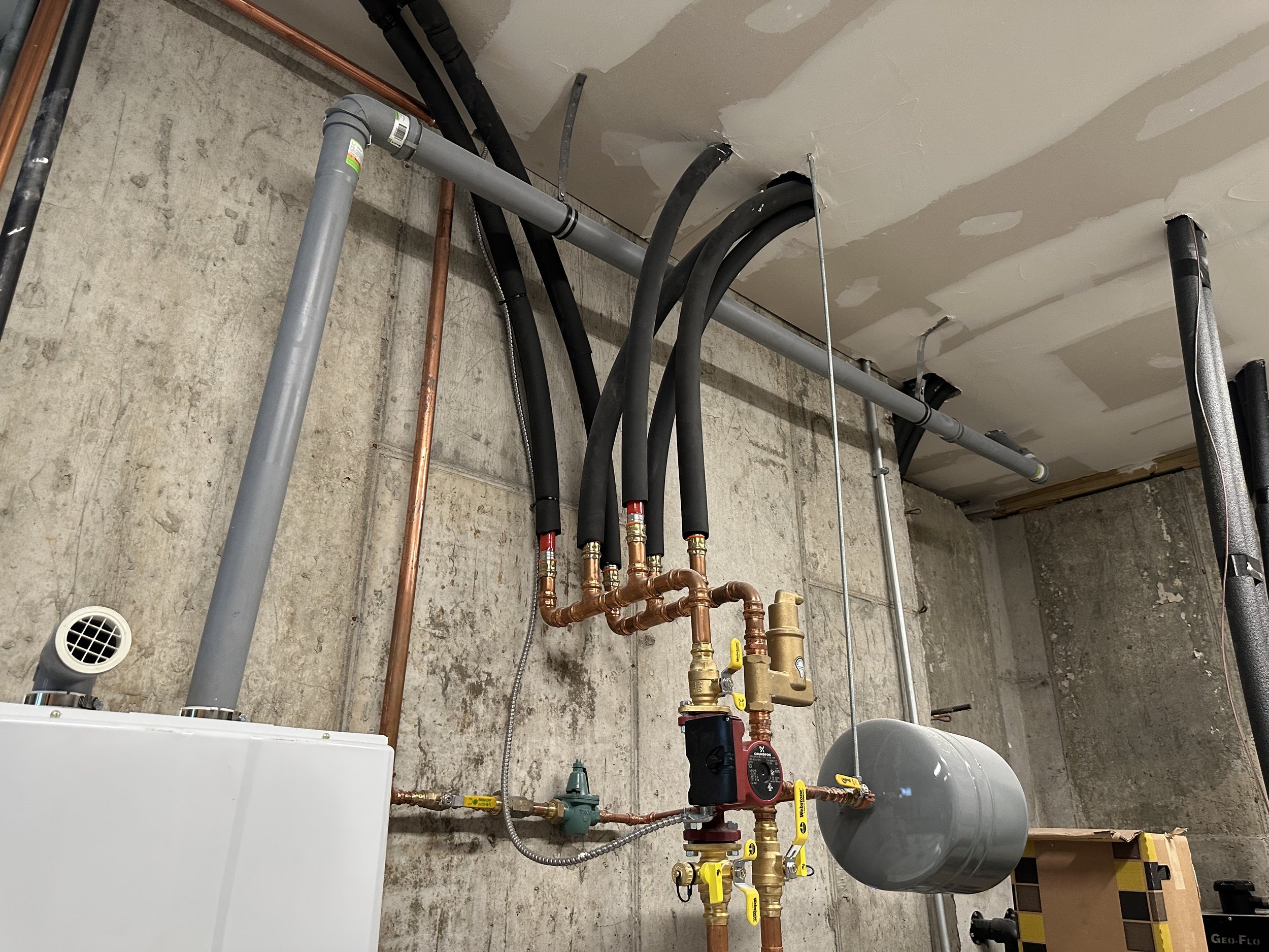
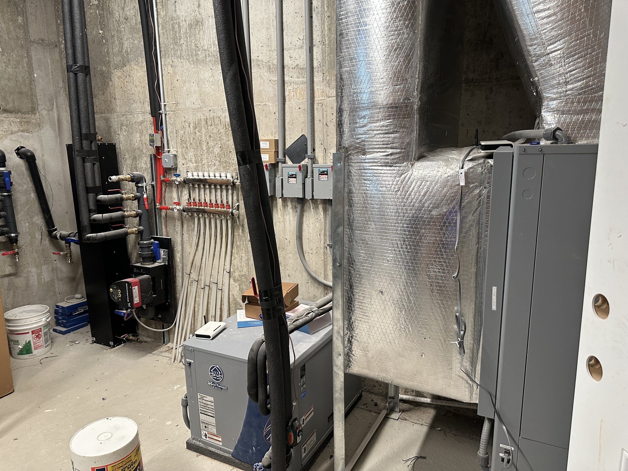


Heat Pump:

A heat pump is a central component of a direct-use geothermal system. It circulates the warm water from the geothermal well to the home and is responsible for extracting heat from the water and transferring it to the home for heating purposes. Heat pumps come in different sizes and configurations, but the most common types used in direct-use geothermal systems are air-source and water-source heat pumps.

Air-source heat pumps use the outdoor air as the source of heat, while water-source heat pumps use the water from the geothermal well. Both types of heat pumps work by using a refrigerant to transfer heat from one location to another. In the case of a direct-use geothermal system, the heat pump circulates warm water from the well to the home and transfers heat to the home's heating system.
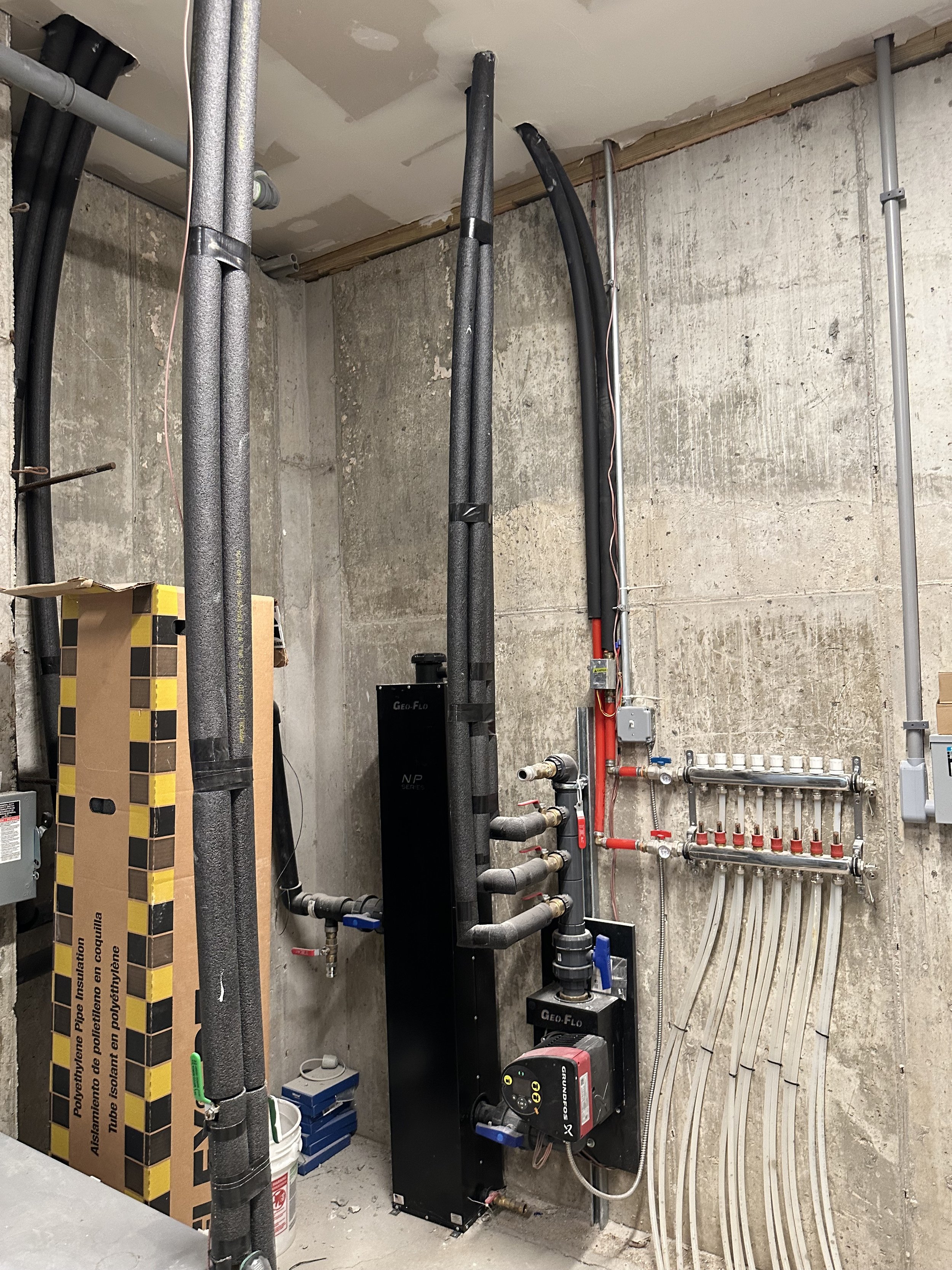
Pipe Insulation:

Pipe insulation is used in a direct-use geothermal system to prevent heat loss as the water is circulated from the geothermal well to the home. The insulation helps to keep the water at a consistent temperature, which improves the efficiency of the system and reduces energy consumption.


There are different types of insulation materials available, including foam insulation, fiberglass insulation, and closed-cell insulation. The type of insulation used will depend on the specific requirements of the system and the local building codes. It is important to use high-quality insulation that is designed for underground use, as it must be able to withstand the harsh conditions of underground installation.

Several types of foam insulation can be used for underground pipes in a direct-use geothermal system, including polyurethane foam and polyethylene foam.


Polyurethane foam is a closed-cell foam that is known for its high insulation value, durability, and resistance to moisture. It is often used for underground pipe insulation due to its excellent thermal performance and ability to withstand the pressure of the surrounding soil.

Polyethylene foam is another common choice for underground pipe insulation. It is a lightweight, flexible, and closed-cell foam that is easy to install and provides good insulation properties. It is also resistant to moisture and has a low thermal conductivity, which makes it a good choice for geothermal applications.

The type of foam insulation used in a direct-use geothermal system will depend on several factors, such as the local building codes, the climate, and the specific requirements of the system. It is best to consult with a professional geothermal contractor to determine the most appropriate type of insulation for your system.


Closed-cell insulation is a type of insulation material that is made up of small, tightly packed cells that are filled with a gas, such as air, or a proprietary blend of gases. The cells are closed, meaning that the gas is trapped inside and cannot circulate freely, providing excellent insulation properties.

Closed-cell insulation is known for its high insulation value, making it a good choice for applications where high thermal performance is required. It is also resistant to moisture, which makes it a good choice for underground installations, such as in a direct-use geothermal system.

Closed-cell insulation is typically denser and stiffer than open-cell insulation, making it a good choice for applications where structural support is required. Additionally, because the cells are closed, it has a higher resistance to air infiltration and can provide a vapor barrier, making it a good choice for applications where airtightness is important.


Overall, closed-cell insulation is a versatile and effective insulation material that is widely used in a variety of applications, including building and construction, industrial and commercial applications, and geothermal systems.


The type of gas used in closed-cell insulation can vary depending on the manufacturer and the specific product. Some of the most common gases used in closed-cell insulation include:

  • Air: Air is the most common gas used in closed-cell insulation and is often used in polyurethane foam insulation.

  • Argon: Argon is an inert, colorless, and odorless gas that is often used in closed-cell insulation due to its excellent insulation properties.

  • Krypton: Krypton is another inert gas that is often used in closed-cell insulation due to its high thermal resistance.

  • Xenon: Xenon is a rare, inert gas that is used in closed-cell insulation due to its high thermal resistance and insulation value.


It is important to note that some manufacturers use proprietary blends of gases to enhance the insulation properties of their products. These blends can be optimized to provide the best combination of insulation value, moisture resistance, and durability.

The specific gas used in closed-cell insulation will depend on the manufacturer, the product, and the specific requirements of the application. Consult with a professional insulation specialist to determine the best type of gas for your needs.


What are the potential hazards of using geothermal energy production?


Yes, there are potential hazards associated with geothermal energy production, although these are generally minor compared to the benefits of this clean, renewable energy source. Some of the most common hazards include:

  • Hydrogen Sulfide Gas: Hydrogen sulfide gas is a byproduct of geothermal energy production and can pose a health risk if not properly managed. In high concentrations, hydrogen sulfide gas can be toxic and can cause respiratory problems, headaches, and dizziness. It is important to install proper ventilation systems and monitor hydrogen sulfide levels to ensure the safe operation of a geothermal energy system.

  • Earth Tremors: Geothermal energy production can sometimes cause small earth tremors, although these are generally minor and do not pose a significant risk. In some cases, geothermal energy production has been associated with increased seismic activity, although this is relatively rare.

  • Environmental Impacts: Geothermal energy production can have impacts on the local environment, including changes to water quality, soil and air quality, and wildlife habitats. It is important to carefully manage and monitor these impacts to ensure that geothermal energy production is sustainable over the long term.

  • Corrosion: Geothermal energy production can result in increased levels of corrosion, which can affect the longevity and performance of equipment and infrastructure. It is important to use corrosion-resistant materials and coatings to prevent this type of damage.

Overall, geothermal energy production is considered to be a relatively safe and environmentally friendly form of energy production, and the hazards associated with this technology are manageable with proper planning and management.


Here are a few companies that install geothermal systems for homes in the Dallas, Texas area:

  1. EcoGeo Solutions

  2. TGE Technologies

  3. Skyline Innovations

  4. Green Energy Solutions

  5. Prime Mechanical

  6. Texas Geothermal Solutions

  7. H&H Environmental Services

  8. Texas Renewable Energy

  9. WaterFurnace Southwest

  10. Earth Energy Solutions


Here are a few companies that install geothermal systems for homes in the New York Tristate area:

  1. Advanced Geothermal Systems

  2. Geothermal Experts

  3. Tri-State Geothermal

  4. Earth Energy Solutions

  5. Green Energy Solutions

  6. Energy Geothermal

  7. Infinity Renewables

  8. Climate Control Heating & Air Conditioning

  9. Naughton Energy

  10. R.A. Snyder Services


Here are a few companies that install geothermal systems for homes in the Los Angeles, California area:


  1. Cal-Tech Heating & Air Conditioning

  2. California Geothermal

  3. Geo-Thermal Solutions

  4. Green Energy Solutions

  5. Sunset Air

  6. SoCal Geothermal

  7. Energy Geothermal

  8. Infinity Renewables

  9. EcoGeo Solutions

  10. LA Geothermal Solutions


It is important to note that this list is not exhaustive, and there may be other companies in these areas that offer geothermal installation services. Before choosing a company, it is recommended that you research their experience and reputation and get multiple quotes to compare prices and services. Additionally, it is recommended that you work with a licensed and insured contractor to ensure the quality and safety of your geothermal system installation.


Here are some potential drawbacks of using geothermal energy for a home:

  1. Initial Costs: Installing a geothermal energy system can be expensive, with costs ranging from $20,000 to $50,000 or more. This may make it less accessible for some homeowners, especially those on a tight budget.

  2. Complexity: Geothermal systems are complex and require specialized knowledge and skills to install and maintain. This can make it difficult for homeowners to perform their own maintenance or repairs and may require them to hire a professional contractor.

  3. Location-specific: Geothermal energy systems require access to geothermal resources, such as hot springs, geysers, or volcanic activity. This means that not all homes will be able to use geothermal energy, and the suitability of the technology will depend on the local geography and geology.

  4. Limited Capacity: Some geothermal systems may have limited capacity and may not be able to generate enough energy to power a home during periods of high demand.

  5. Environmental Concerns: Geothermal energy systems can have some environmental impacts, such as the release of greenhouse gases and changes to water quality in the vicinity of geothermal wells. Additionally, the installation of geothermal systems may result in the disturbance of natural landscapes, including the removal of vegetation and the excavation of land.

It is important to note that these potential drawbacks will vary depending on the specific system, location, and other factors. Before choosing a geothermal energy system, it is important to carefully consider the costs, benefits, and potential drawbacks of the technology and to work with a licensed and experienced contractor to ensure the quality and safety of your installation.


Here are some long-term benefits of using geothermal energy to power a home:

  1. Energy Efficiency: Geothermal systems are highly energy efficient, with efficiency ratings that can be as high as 400%. This means that they can generate more energy than they consume, reducing the amount of energy required from other sources.

  2. Cost Savings: Geothermal systems can result in significant cost savings over time, as homeowners can reduce their dependence on more expensive forms of energy, such as electricity from the grid or heating oil.

  3. Reliability: Geothermal systems are reliable and can provide consistent and continuous heating and cooling with minimal maintenance. This means that homeowners can count on their systems to keep their homes comfortable and energy efficient, even during periods of extreme weather or power outages.

  4. Environmentally Friendly: Geothermal systems are considered to be environmentally friendly, as they produce very low emissions of greenhouse gases and do not rely on the burning of fossil fuels.

  5. Longevity: Geothermal systems are long-lasting and can last for decades with proper maintenance. This makes them a smart investment for homeowners who want to reduce their energy costs and minimize their environmental impact over the long term.


It is important to note that the specific benefits of using geothermal energy to power a home will depend on the specific system, location, and other factors. Before choosing a geothermal energy system, it is important to carefully consider the costs, benefits, and potential drawbacks of the technology and to work with a licensed and experienced contractor to ensure the quality and safety of your installation.


What are the potential electromagnetic issues with using geothermal power for a home?


There are no significant electromagnetic issues associated with using geothermal power for a home. Geothermal systems work by tapping into the heat stored in the earth to provide heating, cooling, and hot water for a home. Unlike other types of energy generation, such as fossil fuels or nuclear power, geothermal systems do not generate significant levels of electromagnetic radiation or interference.

It is important to note that all electrical equipment, including geothermal systems, generates some level of electromagnetic interference, but these levels are typically well within safe limits and do not pose a significant risk to human health or the environment. If you have concerns about electromagnetic interference from your geothermal system, you can work with a licensed and experienced contractor to assess the system and make any necessary modifications to ensure that it operates safely and efficiently.


Are inverters needed to convert DC to AC with geothermal systems?


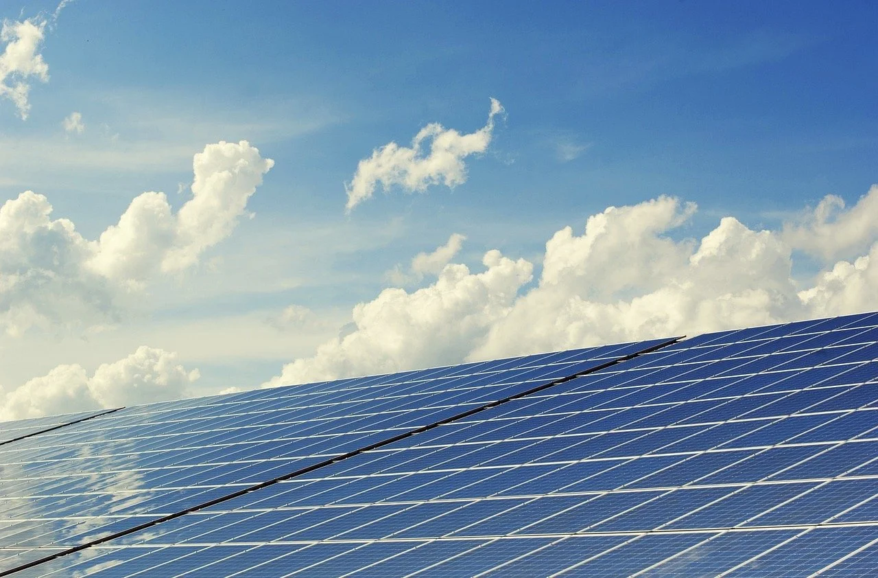
Inverters are not typically needed with geothermal systems. Geothermal systems work by tapping into the heat stored in the earth to provide heating, cooling, and hot water for a home. Unlike solar panels, which generate electricity from the sun, geothermal systems do not generate electricity and do not require inverters to convert DC to AC.

Instead, geothermal systems use a heat pump to transfer heat from the earth to the home, where it is used to provide heating, cooling, and hot water. The heat pump operates using electrical power, but it does not generate electricity and, therefore, does not require an inverter.

If you are interested in using geothermal energy to power your home, it is important to work with a licensed and experienced contractor who can help you assess your specific energy needs and determine the best type of geothermal system for your home. They can also provide information on any additional equipment or components that may be needed to ensure the safe and efficient operation of your geothermal system.


Does the heat pump use a Variable Frequency Drive?


Yes, some geothermal heat pumps use a Variable Frequency Drive (VFD) to control the speed of the system's compressor and circulate refrigerant. The VFD helps to regulate the flow of refrigerant, which in turn helps to optimize the efficiency of the heat pump and reduce energy consumption.

VFDs can also be used to control the speed of the system's fan or pump, depending on the specific design of the heat pump. By using a VFD, the heat pump can operate at an optimal speed to meet the demands of the heating and cooling system, which can help to improve efficiency and reduce energy consumption.

It is important to note that not all geothermal heat pumps use a VFD, and the use of a VFD is dependent on the specific design of the heat pump. If you are interested in using a geothermal heat pump with a VFD, it is recommended that you work with a licensed and experienced contractor who can provide information on the specific heat pump and assist with the installation and operation of the system.


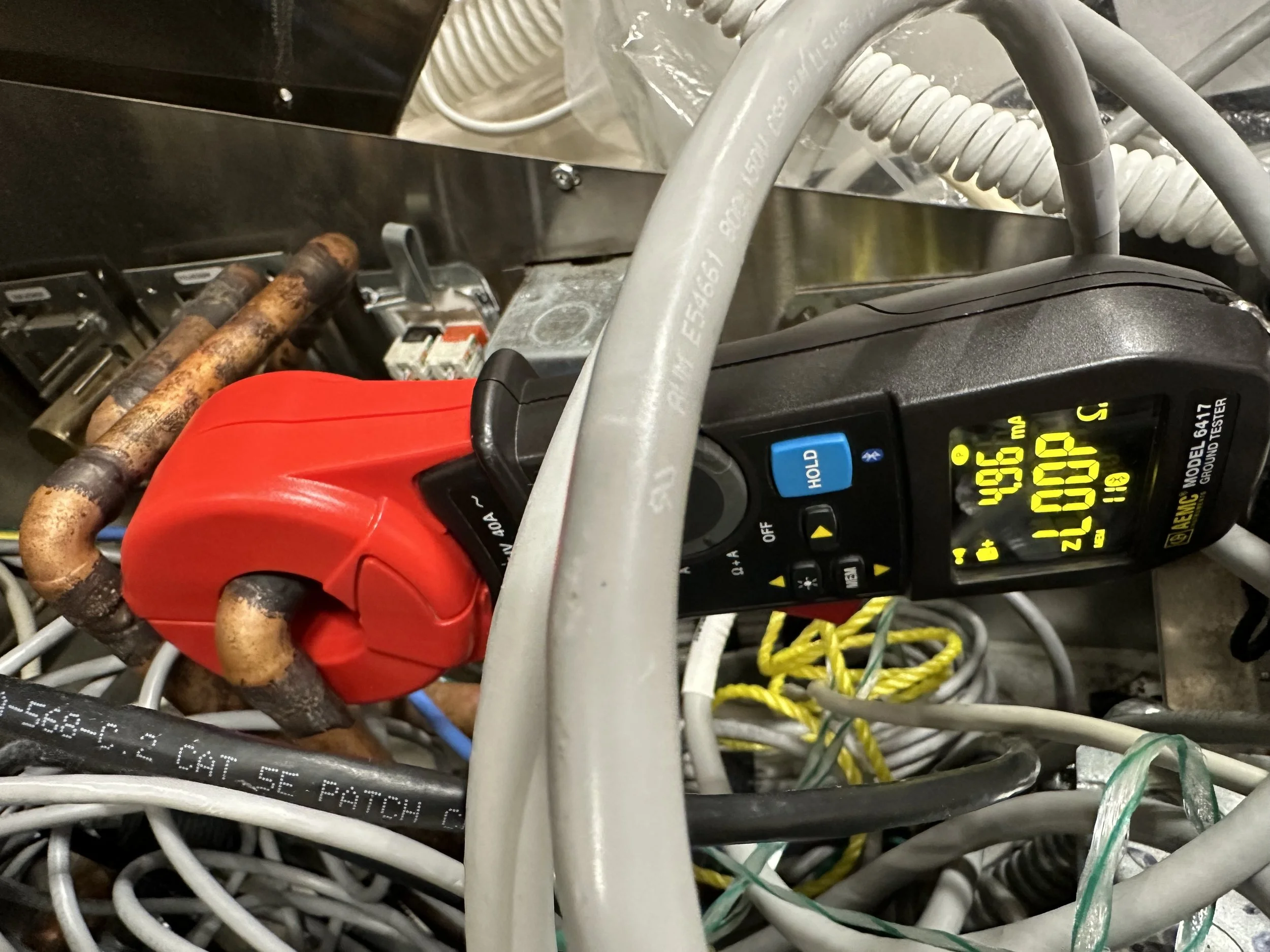
Does the VFD produce EMI?


Variable Frequency Drives (VFDs) can produce Electromagnetic Interference (EMI). EMI is the result of electrical and magnetic fields that are generated by electrical equipment and can interfere with other electronic equipment or devices.

In the case of VFDs, the fast switching of the power electronics within the VFD can generate EMI, which can affect other electronic equipment or devices in the vicinity. However, most VFDs are designed with EMI filtering to reduce the level of interference, and modern VFDs are typically well within the limits established by international standards for EMI.


If you are concerned about the potential for EMI from a VFD in your geothermal heat pump system, it is recommended that you work with an experienced EMI Consultant who can assess the specific VFD and make any necessary modifications to ensure that it operates safely and efficiently. They can also provide information on any additional equipment or components that may be needed to reduce the level of EMI from the VFD.


What are the typical frequencies of variable Frequency Drives for geothermal heat pumps?


The typical frequency range for a Variable Frequency Drive (VFD) in a geothermal heat pump system is between 0 and 60 Hertz (Hz). The exact frequency range of a VFD will depend on the specific design and requirements of the geothermal heat pump system.

The VFD is used to control the speed of the system's compressor or fan, which helps to regulate the flow of refrigerant or air within the heat pump. By adjusting the frequency of the VFD, the speed of the compressor or fan can be increased or decreased as needed, which in turn helps to optimize the performance of the heat pump.

It is important to note that different geothermal heat pump systems may use VFDs with different frequency ranges, and the frequency range of the VFD will depend on the specific design of the heat pump system. If you are interested in using a geothermal heat pump with a VFD, it is recommended that you work with a licensed and experienced contractor who can provide information on the specific VFD and assist with the installation and operation of the system.

Solar Power Inverters and EMI Filtering Techniques; Everything You Need to Know

Whether you are an electrical engineer, an electrician, or a homeowner considering a new solar power system installation, or you already own one, you will eventually need to deal with the resultant electromagnetic interference, EMI.

Regardless of the term you prefer, Signal-to-Noise Ratio (S/N or SNR), THD+N (Total Harmonic Distortion Plus Noise), harmonic transients, ripple, or “dirty electricity,” solar systems emit high amplitudes of transient harmonic voltages from semiconductor switching onto an electrical system, often interfering to varying degrees with the function of your appliances, electrical devices, electronics, and, eventually onto you.

(The basic physics formulas that describe this process are: Δv/Δτ and Δi/Δτ, where Δ = change, τ = time interval, v = voltage differences, i = current differences.)

Alternative energy is now more popular than ever, and there is much to learn. In the next few months, I plan to share essential knowledge about each type and how to mitigate the electromagnetic interference they produce.

Solar Power is by far the alternative energy source most often asked about. Solar panels produce direct current (DC) electricity, which is incompatible with the alternating current (AC) electricity used in homes. To use the electricity produced by solar panels, it must be converted from DC to AC.

Here is the basic process to convert solar energy into usable AC electricity for a home:

  1. Sunlight: The sun provides the energy source for the solar photovoltaic cells.

  2. Solar Photovoltaic Cells: The photovoltaic cells within a series of photovoltaic (PV) panels are installed on the roof or in a suitable location with unobstructed access to sunlight. The panels convert the sunlight into direct current (DC) electricity.

  3. DC to AC Inverter: The DC electricity from the panels is sent to a solar inverter, which converts the DC electricity into alternating current (AC) electricity. The inverter is typically located near the electrical service panel in the home.

  4. Electrical Service Panel: The AC electricity is then sent to the home's electrical service panel, which is then distributed to the various electrical branch circuits in the home.

  5. Energy Metering: A bi-directional meter is installed to monitor the flow of electricity between the home and the electrical grid. This meter allows the homeowner to determine how much electricity is being produced by the solar panels and how much is being drawn from the grid.

  6. Electrical Grid Connection: The home is connected to the electrical grid through a power company-owned utility line. This allows the home to receive electricity from the grid when the demand exceeds the supply from the solar panels and to send excess electricity back to the grid when the panels are producing more electricity than the home is using.

  7. ESS: (Energy Storage System) is a device that stores excess energy generated by a solar power system. The stored energy can be used later to meet the energy demand when the solar panels are not producing enough energy (e.g., during nighttime or cloudy conditions). An ESS typically consists of batteries or other energy storage technologies and may include power electronics and control systems. Using an ESS can increase the overall efficiency of a solar power system and provide a more reliable and stable energy supply.

    Some popular brands and models of ESS for home use:

    • Tesla Powerwall: This is a lithium-ion battery system designed for residential use and is one of the most well-known ESSs on the market.

    • LG Chem RESU: This is a high-capacity lithium-ion battery system compatible with a wide range of inverters and can be easily integrated into a home solar power system.

    • Sonnen: Sonnen offers several ESS models for residential use, including the SonnenBatterie and the SonnenCore. These systems are designed to work in tandem with solar panels and provide energy storage and backup power.

    • Enphase Energy Storage System: This is a modular battery system that can be added to an existing Enphase solar power system. It uses lithium-ion batteries and has a scalable design, making it suitable for homes of different sizes.

    These are just a few examples of ESSs that are available for residential use. When choosing an ESS for your home, it's important to consider factors such as capacity, compatibility with your existing solar power system, and the local regulations and incentives for energy storage.

(A licensed electrical contractor should be consulted for a detailed design and installation to ensure compliance with local codes and standards.)

The conversion process is accomplished by using an inverter. An inverter takes the DC electricity from the solar panels and converts it into AC electricity. The inverter is usually installed near the solar panels and is connected to the panels through cables. The DC electricity from the panels flows into the inverter and is then converted into AC electricity.

When choosing an inverter, it is important to consider the following factors:

  1. Power capacity: The inverter must have the capacity to handle the amount of electricity produced by the solar panels.

  2. Efficiency: An efficient inverter will produce less heat and more efficiently convert DC to AC electricity.

  3. Grid compatibility: Inverters are designed to be compatible with the electrical grid in your area. It is important to choose an inverter that is compatible with your local electrical grid.

  4. Size: The inverter must be appropriately sized for the amount of electricity produced by the solar panels.

By converting DC solar to AC electricity, homes can use the clean and renewable energy produced by their solar panels to power their homes. This not only reduces their carbon footprint but also saves on electricity costs.

Reducing line noise or Electromagnetic Interference (EMI) is integral to the DC-to-AC conversion process.

Here are a few steps that can be taken to reduce EMI:

  1. Proper grounding: Ensure that the inverter is properly grounded to minimize the risk of EMI.

  2. Quality components: Use high-quality components in the inverter circuit to reduce EMI.

  3. Shielding: Shield the inverter and cables with metal casing or braided shielding to reduce the emission of EMI.

  4. Ferrite beads: Place ferrite beads on the DC and AC cables to absorb EMI.

  5. Filtering: Implement appropriate filtering in the inverter circuit to reduce EMI.

  6. Proper installation of the inverter and cables will also reduce EMI.

Reducing EMI is important to ensure that the electrical system remains stable and does not interfere with other electrical equipment. By taking these steps, you can reduce the risk of EMI and ensure that your DC to AC-conversion process is efficient and reliable.

Here are a few EMI filters commonly used in DC to AC conversion applications:

  • Common-Mode Choke: A common-mode choke is a type of inductor placed on the DC and AC cables to absorb EMI. It is typically used in pairs, one placed on the positive line and one on the negative line, to reduce the common-mode noise on both lines. The choke consists of a wire coil wound around a magnetic core. The magnetic core is designed to increase the coil's inductance, which helps reduce the flow of high-frequency noise.

    A common-mode choke provides a low impedance path for the common-mode noise, which helps reduce the amount of noise transmitted from the power source to the equipment. The choke acts as a filter, absorbing the high-frequency noise and reducing the amount of EMI in the system.

    Common-mode chokes are a simple, effective, and reliable solution for reducing EMI in electrical systems and are widely used in various applications, such as DC to AC power inverters, power supplies, and motor drives. They are particularly useful in applications with high common-mode noise, providing a cost-effective solution for reducing this noise.

  • Pi Filter: A Pi filter is a type of LC filter placed on the AC output of the inverter to reduce EMI. It is a passive circuit that consists of two inductors (L) and two capacitors (C) arranged in a Pi configuration.

    The Pi filter works by reducing high-frequency noise in the system. The inductors act as choke coils, limiting the flow of high-frequency noise, while the capacitors act as bypasses, short-circuiting the high-frequency noise and passing it to ground.

    The Pi filter is often used in applications where the requirement for EMI reduction is high, such as in DC to AC power inverters, power supplies, and motor drives. The Pi filter can be customized to meet the application's specific requirements, such as the frequency range and the level of EMI reduction required.

    The Pi filter is a simple, cost-effective, and reliable solution for reducing EMI in electronic systems. It is widely used in various applications and is considered a standard solution for EMI reduction.

  • Common-Mode Filter: A common-mode filter is a type of filter that is placed on the AC output of the inverter to reduce EMI. A common-mode filter is an EMI (Electromagnetic Interference) filter used to suppress common-mode noise in electrical systems. It works by suppressing the differential-mode noise and passing the common-mode noise through capacitors and inductors.

    The components of a common-mode filter include:

    • Chokes (Inductors): These components limit the flow of high-frequency noise.

    • Capacitors: These components provide a low-impedance path to ground for high-frequency noise.

    • Ferrite Beads: These components act as high-frequency low-pass filters and provide additional EMI suppression.

    The common-mode filter is connected in parallel with the power or signal lines to be protected, with the positive side connected to one line and the negative side connected to the other line. The combination of inductors and capacitors in the filter creates a low-impedance path for common-mode noise, effectively filtering it out of the signal.

  • Line Filter: A line filter is an EMI filter placed on the AC input of the inverter to reduce EMI. These filters can be selected based on the specific requirements of the application, such as the amount of EMI reduction required, the type of electrical equipment that needs to be protected, and the cost and availability of the filters. Usually, a combination of these filters is used to achieve the desired level of EMI reduction.

    A line filter is typically placed between the power source and the equipment being powered to reduce the amount of high-frequency noise transmitted from the power source to the equipment. Line filters are an effective and reliable solution for reducing EMI in electrical systems and are widely used in various applications.

A typical Line Filter consists of the following components:

  1. Inductor(s): One or more inductors are used to limit the flow of high-frequency noise, which acts as a choke coil.

  2. Capacitor(s): One or more capacitors are used to short-circuit the high-frequency noise, which acts as a bypass.

  3. Resistor(s): One or more resistors are used to provide damping to the filter, which helps to reduce ringing and overshoot.

  4. Metal casing: The components are housed in a metal casing to provide shielding and to reduce the emission of EMI.

The number and values of the components can vary depending on the application's specific requirements, such as the frequency range and the level of EMI reduction required. Line filters can also be designed to meet specific equipment requirements, such as motor drives, power supplies, and DC to AC inverters.

  • Differential-Mode Filter: A differential-mode filter is placed on the DC input of the inverter to reduce EMI. A differential-mode filter is another EMI (Electromagnetic Interference) filter that reduces noise in electrical systems. It is designed to reduce the differential-mode noise between two lines, such as the positive and negative lines in a power supply.

    A Differential-Mode Filter typically consists of the following components:

    1. Inductor(s): One or more inductors are used to limit the flow of high-frequency noise, which acts as a choke coil.

    2. Capacitor(s): One or more capacitors are used to short-circuit the high-frequency noise, which acts as a bypass.

    3. Resistor(s): One or more resistors dampen the filter, which helps reduce ringing and overshoot.

    Again, the number and values of the components can vary depending on the application's specific requirements, such as the frequency range and the level of EMI reduction required. The inductors limit the flow of high-frequency noise, while the capacitors short-circuit the high-frequency noise and pass it to ground. The resistors provide damping, which helps to reduce ringing and overshoot.

There are several types of inverters used to convert DC to AC, including:

  1. Square Wave Inverter: generates a square wave output with abrupt transitions between the positive and negative voltages.

    Advantages: Simple design, low cost.

    Disadvantages: Poor power quality, increased harmonic distortion, inefficient operation of some electrical devices.

  2. Modified Sine Wave Inverter: generates a waveform that approximates a sine wave, with smoother transitions than a square wave.

    Advantages: Improved power quality compared to a square wave inverter and lower cost compared to a pure sine wave inverter.

    Disadvantages: Still inferior power quality compared to a pure sine wave inverter, increased harmonic distortion.

  3. Pure Sine Wave Inverter: generates a waveform that is a close representation of a true sine wave.

    Advantages: High power quality, efficient operation of all electrical devices, low harmonic distortion.

    Disadvantages: More complex and expensive design compared to other types.

  4. Pulse Width Modulation (PWM) Inverter: uses digital signals to generate an AC output by switching the DC voltage on and off at a high frequency.

    Advantages: High power quality, high efficiency, and low harmonic distortion.

    Disadvantages: Complex design, the higher cost compared to other types.

A Pulse Width Modulation (PWM) Inverter typically consists of the following components:

  1. DC source (e.g. battery)

  2. Power electronic switches (e.g. MOSFETs, IGBTs)

  3. Inductor or transformer

  4. Capacitor

  5. Control circuit (e.g. microcontroller, gate driver circuit)

  6. Protection circuit (e.g. over-voltage, over-current)

  7. Output filter to smooth the PWM waveform into a sinusoidal waveform.

A MOSFET (Metal-Oxide-Semiconductor Field-Effect Transistor): is a power electronic switch that controls the flow of electric current by using an electric field. MOSFETs are widely used in inverters due to their fast switching speeds, high efficiency, and simple drive requirements. (More info on MOSFETs in the Addendum.)

An IGBT (Insulated-Gate Bipolar Transistor): is another power electronic switch that combines the benefits of a bipolar transistor and a MOSFET. IGBTs are capable of handling high current and voltage levels, and they have fast switching speeds like MOSFETs. This makes them ideal for high-power inverter applications where high efficiency and high power density are desired. (More info on IGBTs is in the Addendum.)

The Protection Circuit in a PWM inverter is designed to prevent damage to the inverter components and to ensure the safe operation of the system. Protection circuits are typically used to detect and respond to over-voltage, over-current, short-circuit, and thermal conditions.

  1. Over-Voltage Protection: Detects and responds to high voltage levels in the inverter output, which can damage the components or cause safety issues.

  2. Over-Current Protection: Detects and responds to high current levels in the inverter output, which can cause overheating and damage to the components.

  3. Short-Circuit Protection: Detects and responds to a short-circuit condition in the inverter output, which can cause high current levels and damage the components.

  4. Thermal Protection: Detects and responds to high-temperature levels in the inverter components, which can cause overheating and permanent damage.

When these protection events occur, the protection circuit typically shuts down the inverter operation or reduces the output power to prevent further damage. The protection circuit is an important component in ensuring the safe and reliable operation of the PWM inverter.

In a Pulse Width Modulation (PWM) inverter, the type of capacitor is typically an electrolytic capacitor. These capacitors are used in the output filter circuit to smooth the PWM waveform into a sinusoidal waveform. The capacitance value and voltage rating of the capacitor depending on the power rating and operating conditions of the inverter.

Electrolytic capacitors are preferred for PWM inverters because of their high capacitance density and relatively low cost. Additionally, electrolytic capacitors have a relatively low equivalent series resistance (ESR), which is important for reducing switching losses and improving the overall efficiency of the inverter.

Other types of capacitors, such as tantalum capacitors, may also be used in PWM inverters. However, these capacitors are typically more expensive and have lower capacitance density than electrolytic ones.

In a Pulse Width Modulation (PWM) inverter, the type of transformer is typically an isolation transformer. The purpose of the isolation transformer is to provide electrical isolation between the input DC voltage and the output AC voltage.

The isolation transformer serves several important functions in the PWM inverter, including:

  1. Reducing the voltage stress on the power electronic switches.

  2. Improving the safety of the inverter by preventing electrical shock and fire hazards.

  3. Reducing electromagnetic interference (EMI) generated by the inverter.

Isolation transformers are designed with specific characteristics based on the power rating and operating conditions of the inverter. The primary winding is connected to the input DC voltage, while the secondary winding is connected to the output AC voltage. The transformer's turn ratio is designed to step up or down the voltage to the desired level.

The isolation transformer is an important component in ensuring the reliability and performance of the PWM inverter.

A Pulse Width Modulation (PWM) inverter typically uses an LC (Inductor-Capacitor) output filter to smooth the PWM waveform into a sinusoidal waveform. The LC filter consists of an inductor and a capacitor connected in series or parallel. The LC filter is designed to reduce the harmonic content of the PWM waveform by filtering out high-frequency components and passing the desired sinusoidal waveform.

The LC Filter removes high-frequency harmonic content from the output waveform of the inverter, resulting in a smoother, more sinusoidal waveform. The inductors store energy and block the high-frequency harmonics, while the capacitors serve to smooth the waveform and prevent high-frequency oscillations.

The type of LC filter used in a PWM inverter depends on the power rating, operating frequency, and other specifications of the inverter. The LC filter components are selected based on their frequency response, impedance, and stability characteristics.

The LC filter is an important component in ensuring the performance and efficiency of the PWM inverter by improving the waveform quality and reducing harmonic distortion.

Examples of LC filters used in PWM inverters include:

  1. Series LC Filter is a type of output filter used in power electronics to smooth and shape the output waveform of a power inverter. It comprises an inductor (L) and a capacitor (C) connected in series.

    A series LC filter is a simple and effective way to improve the waveform quality of a power inverter. However, it may not be as effective in removing high-frequency harmonics as a more complex filter, such as a cascaded LC filter or a Pi filter.

    Series LC filters are commonly used in low-power applications where a simple, low-cost solution is desired, such as small inverters or battery chargers.

  2. Parallel LC Filter is a type of output filter used in power electronics to smooth and shape the output waveform of a power inverter. It comprises an inductor (L) and a capacitor (C) connected in parallel.

    The LC filter removes high-frequency harmonic content from the output waveform of the inverter, resulting in a smoother, more sinusoidal waveform. The inductor blocks high-frequency harmonics and the capacitor serves to smooth the waveform and prevent high-frequency oscillations.

    A parallel LC filter is a simple and effective way to improve the waveform quality of a power inverter. A parallel filter may not be as effective in removing high-frequency harmonics as a more complex filter, such as a series LC filter or a Pi filter.

    Parallel LC filters are commonly used in low-power applications where a simple, low-cost solution is desired, such as small inverters or battery chargers.

  3. Cascaded LC Filter is a type of output filter used in power electronics to smooth and shape the output waveform of a power inverter. It is comprised of multiple stages of inductors (L) and capacitors (C) connected in series, hence the name "cascaded LC filter."

    In a cascaded LC filter, multiple stages of LC components are used to filter the output waveform better. This improves the waveform quality, reduces harmonic distortion, and improves the power inverter's overall efficiency and reliability.

    Cascaded LC filters are commonly used in applications that require a clean and stable output waveform, such as uninterruptible power supplies (UPS), renewable energy systems, and motor drives.

A Pure Sine Wave Inverter consists of the following components:

  1. DC-AC Converter: Converts the input DC voltage into a sinusoidal AC voltage.

  2. Output Filter: Smooths the AC waveform and reduces harmonic content.

  3. Control Circuit: Regulates the output voltage and frequency and monitors the inverter for protection events.

The DC-AC Converter in a pure sine wave inverter typically uses the carrier-based pulse width modulation (PWM) technique. This technique converts the DC voltage into a high-frequency sinusoidal waveform, filtered and amplified to produce the desired AC voltage.

A Pure Sine Wave Inverter is a type of inverter that converts direct current (DC) into a sinusoidal alternating current (AC) waveform. Unlike a Pulse Width Modulation (PWM) inverter, which generates a square waveform that resembles a sinusoidal waveform, a pure sine wave inverter generates a true sinusoidal virtually indistinguishable from a utility-supplied AC waveform.

Compared to a PWM inverter, a pure sine wave inverter typically has a more complex control circuit and requires more sophisticated components, such as high-frequency power transistors and specialized output filters. However, the output waveform quality of a pure sine wave inverter is significantly better than that of a PWM inverter, making it suitable for applications that require a clean, reliable power source.

In addition to its improved waveform quality, a pure sine wave inverter provides improved efficiency, reduced noise, EMI, and better compatibility with sensitive loads, such as computers and audio equipment.

Some popular brands and models of Pure Sine Wave Inverters include:

  1. Victron Energy Phoenix Inverters

  2. Outback Power FlexMax Inverters

  3. Xantrex Freedom Inverters

  4. Schneider Electric XW Inverters

  5. SMA Sunny Boy Inverters

  6. EcoFlow Delta Inverter Generators

  7. Inverter Generators by Yamaha and Honda

These brands and models offer a range of power ratings and features, including compact design, high efficiency, low noise, and remote monitoring capabilities. These inverters are widely used in various applications, including off-grid and mobile power systems, backup power, and commercial and industrial power solutions. The specific model and brand will depend on the user's requirements and application.

Some popular brands and models of Pulse Width Modulation (PWM) inverters include:

  1. PowerBright PW1100-12

  2. KRIËGER 1100 Watt 12V Power Inverter

  3. Energizer EN1100

  4. AMPEAK 1000W Power Inverter

  5. BESTEK 500W Power Inverter

  6. Go Power! GP-SW1000-12

  7. AIMS Power PWRI110012

These brands and models offer a range of power ratings and features, including compact design, high efficiency, low noise, and remote monitoring capabilities. These inverters are widely used in various applications, including off-grid and mobile power systems, backup power, and commercial and industrial power solutions. The specific model and brand will depend on the user's requirements and application.

Pi Filter Diagram © 2023

Addendum:

  1. The Pi Filter is a type of output filter used in power electronics to smooth and shape the output waveform of a power inverter. It gets its name from its shape, which resembles the Greek letter "π" and consists of two inductors (L) and a capacitor (C) connected in a specific arrangement. The inductors block high-frequency harmonics, while the capacitor serves to smooth the waveform and prevent high-frequency oscillations.

In the diagram, L1 and L2 represent the inductors, and C1 represents the capacitor. The inductors are connected in series, with their common connection connected to the capacitor. The other terminal of L1 is connected to the inverter output, while the other terminal of L2 is connected to ground. The other terminal of the capacitor is also connected to the inverter output.

The topology of a Pi filter can be represented as follows: two inductors are connected in series, with the common connection of the two inductors being connected to a capacitor. The other terminal of the first inductor and the other terminal of the capacitor is connected to the inverter output. In contrast, the other terminal of the second inductor is connected to ground.

The Pi filter is a more complex and effective filter than a series LC filter or a parallel LC filter. It is commonly used in applications that require a clean and stable output waveform, such as uninterruptible power supplies (UPS), renewable energy systems, and motor drives.

MOSFET Diagram © 2023


2. The operation of the MOSFET is based on the flow of charge carriers (electrons or holes) through a channel between the source and the drain, which is controlled by the voltage applied to the gate terminal. The gate terminal is insulated from the channel and is connected to the body, allowing the charge carriers to flow between the source and drain.

When a positive voltage is applied to the gate terminal, it attracts electrons and forms an inversion layer in the channel, which enhances the conductivity between the source and drain. When a negative voltage is applied to the gate terminal, it repels electrons and reduces the conductivity between the source and drain.

MOSFETs are widely used in power electronics due to their high input impedance, fast switching speed, and low on-state resistance, making them ideal for high-frequency switching applications, such as PWM inverters.

Here is a diagram that represents the basic structure of a MOSFET. In the diagram, the MOSFET has three terminals: the source (S), the drain (D), and the body (B). The source and drain form the input/output of the MOSFET, while the body is connected to the substrate or the source.

IGBT diagram © 2023

3. IGBTs are widely used in power electronics due to their high voltage and current capabilities, fast switching speed, and low on-state voltage drop, making them ideal for high-power switching applications, such as PWM inverters and UPS systems.

The operation of the IGBT is based on the flow of charge carriers (holes and electrons) between the emitter and collector, which is controlled by the voltage applied to the base terminal. When a positive voltage is applied to the base terminal, it causes holes to flow from the emitter to the base, creating a high current flow from the collector to the emitter, turning on the IGBT. When the voltage is removed from the base, the holes stop flowing, turning off the IGBT.

Here is a diagram that represents the basic structure of an IGBT. In the diagram, the IGBT has three terminals: the emitter (E), the collector (C), and the base (B). The emitter and collector form the input/output of the IGBT, while the base is connected to the p-n junction of the device.

What are the potential long-term drawbacks of using solar power for a home?

Here are some potential long-term drawbacks of using solar power for a home:

  1. Initial Costs: Installing a solar energy system can be expensive, ranging from $10,000 to $30,000. This may make it less accessible for some homeowners, especially those on a tight budget.

  2. Maintenance: Solar panels require regular cleaning and maintenance to maintain their efficiency. This may require homeowners to invest time and money into keeping their systems in good working order.

  3. Location Dependency: The efficiency of solar panels can be affected by weather conditions, such as cloud cover, dust, and other environmental factors. This means that homeowners may experience reduced energy generation during inclement weather.

  4. Energy Storage: Solar panels generate electricity during daylight hours but may not generate enough energy to meet the needs of a home during periods of low light or at night. This means that homeowners may need to invest in energy storage systems, such as batteries, to ensure that they have a reliable energy source when needed.

  5. Incompatible with Older Homes: Solar panels may not be suitable for older homes with limited roof space or outdated electrical systems and may require homeowners to make significant upgrades to accommodate the technology.

  6. Interference with Other Technologies (if you do not preemptively remediate EMI): Solar panels may interfere with other technologies, such as radio or television signals, or cause electromagnetic interference. This may result in performance issues or other problems that can be difficult and expensive to resolve.

It is important to note that these potential drawbacks will vary depending on the specific system, location, and other factors. Before choosing a solar energy system, it is important to carefully consider the costs, benefits, and potential drawbacks of the technology and to work with a licensed and experienced contractor to ensure the quality and safety of your installation.

What are the long-term benefits of using solar power for a home?

Here are some long-term benefits of using solar power for a home:

  1. Cost Savings: By generating their electricity, homeowners who use solar power can reduce their dependence on traditional energy sources, such as the grid, and save money on energy bills over time.

  2. Energy Independence: Solar power systems allow homeowners to generate their electricity, making them less dependent on traditional energy sources, such as the grid. This can provide greater energy security, especially in areas where power outages are common.

  3. Environmentally Friendly: Solar power is a clean and renewable energy source that produces no emissions or pollution. This makes it an environmentally friendly option for homeowners who want to reduce their carbon footprint.

  4. Low Maintenance: Solar panels are low maintenance and require minimal cleaning and upkeep, making them a hassle-free option for homeowners who want to generate their electricity.

  5. Increase Property Value: Homes equipped with solar power systems are often seen as more valuable and appealing to potential buyers, which can increase the property's value over time.

  6. Federal and State Incentives: There are federal and state tax credits, rebates, and other incentives available for homeowners who install solar power systems, which can help offset the initial costs of installation and make the technology more accessible.

It is important to note that the specific benefits of using solar power to electric power a home will depend on the specific system, location, and other factors. Before choosing a solar energy system, it is important to carefully consider the costs, benefits, and potential drawbacks of the technology and to work with a licensed and experienced contractor to ensure the quality and safety of your installation.

© 2023. All rights are reserved.

EMF Testing Meters: Professional vs. Amateur

The AlphaLab Inc. UHS2, costing nearly $400, is a good amateur and semi-pro meter for measuring AC magnetic fields. It can be NIST-certified as a reference meter by AlphaLab Inc.

EMF Testing for health has become increasingly popular around the world. Several retail companies such as Safe Living Technologies, LessEMF, Amazon, Grainger, and others sell consumer-level (amateur) meters, which are easy to use for obtaining a general sense of one’s exposure.

These meters can range from $150 to about $2,000. Should you buy one?

The answer is: yes, and no. It depends on your needs.

If you want a general sense of whether you are moving closer or further from a strong field your meter is designed to measure, then yes. The numbers you read on the meter will only be a reference to compare with other readings you have taken, but the meter will help you learn.

Most consumer-level meters tend not to be accurate at all. Many can not be calibrated. Some “manufacturer-calibrated” meters tend not to hold their calibration very long. Their calibrations certainly will not last one year. This quality of meters can provide readings ranging from 2-20 times higher or lower than the actual amplitudes.

Some more expensive manufacturer-calibrated meters can hold their original calibration for several years, such as the Gigahertz Solutions meters used by many of the members of the Building Biology® Institute. (Note: We have not yet found an ISO 9001 calibration lab in the USA that can provide an ISO 17025 calibration for the Gigahertz Solutions NFA1000. Consequently, we can only use these excellent Near-Field Analyzers in limited applications. We use higher-tier professional equipment for verifiable measurements required in official reports.)

Suppose you need numbers to send your building manager, local power company, town board, or anyone else you need to take action. In that case, a manufacturer-calibrated meter will not be sufficient. (But, even if you had a professional meter, it could still provide inaccurate results unless you are appropriately trained to use it and know how to measure and assess an electromagnetic field correctly.)

So, what is a professional EMF meter?

Well, here again, it depends on your needs. If you are taking general measurements to provide some remediation, a NIST (National Institute of Standards) certified-calibrated meter will ensure that your meter is accurate enough to use as a reference. This means that your meter was compared to another one that was traceable to a NIST-calibrated meter. The meter used to calibrate your meter may not have been the original NIST calibrated meter, and that original meter may no longer be NIST calibrated either. This is why you must ensure your meter is NIST-certified by an ISO 17025 or ISO 9001 lab.

These ISO 17025 and 9001 labs are inspected annually, and their calibration tools are tested and calibrated by a licensed inspector. The people calibrating your meters are also vetted and approved as competent.

So, now, is your meter a professional meter?

Perhaps, but not necessarily for all needs.

Suppose you need measurements that demand professional-level accuracy for replicable studies, verifiable reports, and high-risk measurements. In that case, you need an accredited ANSI/NCSL Z540-1 or ISO 17025 certified-calibrated tool.

And, if you need readings to send to your building manager, condo board, local power company, township trustees, science or engineering staff, or anyone else whom you need to appeal for action, then you will need a meter certified-calibrated to the ISO 17025 standard and hire someone who can measure correctly and submit a bullet-proof report.

The difference between a NIST-certified reference meter and an ISO 17025 or ANSI/NCSL Z540-1 certification, other than the ensured quality of the calibration lab, is the rigorous and detailed level of testing these meters undergo and the detail of the certification testing reported results. These reports will provide accuracy at either dB +/- or the percentage of accuracy for each frequency the tool is calibrated and/or the levels of power it measured at these frequencies.

Depending on the build quality, functional capabilities, and accuracy, professional meters like those we use at Elexana cost ten-of-thousands of dollars each. And, each year, we spend well beyond $10,000 in calibration costs.

Suppose you intend to hire an “expert” to provide you with professional-level numbers. In that case, you need someone who is properly trained to measure, has several years of measuring experience and brings ANSI/NCSL Z540-1 or ISO 17025 certified-calibrated equipment with up-to-date certificates.

ANSI, IEEE, ISO/IEC, CISPR, EN, CEN, CENELEC, and ETSI standards recommend up-to-date certified-calibrated certificates included within final reports or made available upon request, or your report may not be counted on for accuracy; therefore, rendered as unreliable. The report would certainly not hold up for accreditation or verifiability.

© 2022 All rights are reserved.


Infrared Scanning: Not Recommended for Detecting Wiring Errors

Infrared scanning of a ground well shows all is OK, but there is a budding induction issue that will eventually cause a problem. Infrared scanning is simply not enough and anyone who bases their entire electrical assessment on infrared is cutting corners that will leave you vulnerable.

We use infrared technology in specific situations. One use is for displaying the resultant heat caused by wiring errors, but this is only to check if the situation is dire and needs immediate emergency level attention.

If you have a home inspector who only uses infrared for detecting wiring errors, the chances are that they will miss 95% or more of all wiring errors. This is because the heat generated by a loose termination, incorrect gauge for the load, or other wiring issues may not present themselves until long after you have had the inspection.

Also, magnetic fields can fester for years before they generate enough heat to present a significant infrared reading. So, in conclusion, if you have someone inspect your wiring with only an infrared tool, then know that this is an inadequate assessment of your electrical system and you are leaving yourself and your family vulnerable to living with uncorrected wiring errors, unsolved magnetic radiation, and the potential for a shock and fire hazard after the inspector has left your property.

Again, you want to only hire a Building Biology® Institute Certified EMRS, Professional Electromagnetic Radiation Specialist. An EMRS is trained to properly identify, assess, and provide solutions to your electrician for correcting any wiring error issue.

© 2022 All rights are reserved.