Tokamak Magnet Systems: Types, Materials, Manufacture, Metrology, Confinement Role, and Facility Impacts
by James Finn © Copyright 2026 All Rights are Reserved.
Abstract— Tokamak magnets are the core hardware of magnetic-confinement fusion. Their job is not merely to “make a strong field,” but to generate a precisely shaped toroidal-poloidal field system that initiates plasma current, confines charged particles, stabilizes plasma position, and corrects field errors. Modern tokamaks use several magnet classes—toroidal field coils, poloidal field coils, central solenoids, and correction or in-vessel control coils—built from cryoresistive copper, low-temperature superconductors such as NbTi and Nb3Sn, or increasingly high-temperature superconductors such as REBCO. Their design is dominated by extreme electromagnetic forces, cryogenic conditions, insulation, dimensional tolerances, quench-protection, and radiation-damage constraints. This article summarizes the principal magnet types, representative materials and fabrication methods, field levels and sizes, qualification and metrology methods, safety issues, and the likely effects of energized tokamak magnets on buildings, electrical systems, equipment, aircraft compasses, wildlife, and nearby ferromagnetic structures.
Index Terms— Tokamak, superconducting magnet, toroidal field coil, central solenoid, poloidal field coil, REBCO, NbTi, Nb3Sn, quench protection, magnetic diagnostics, remanence, stray field.
I. Introduction
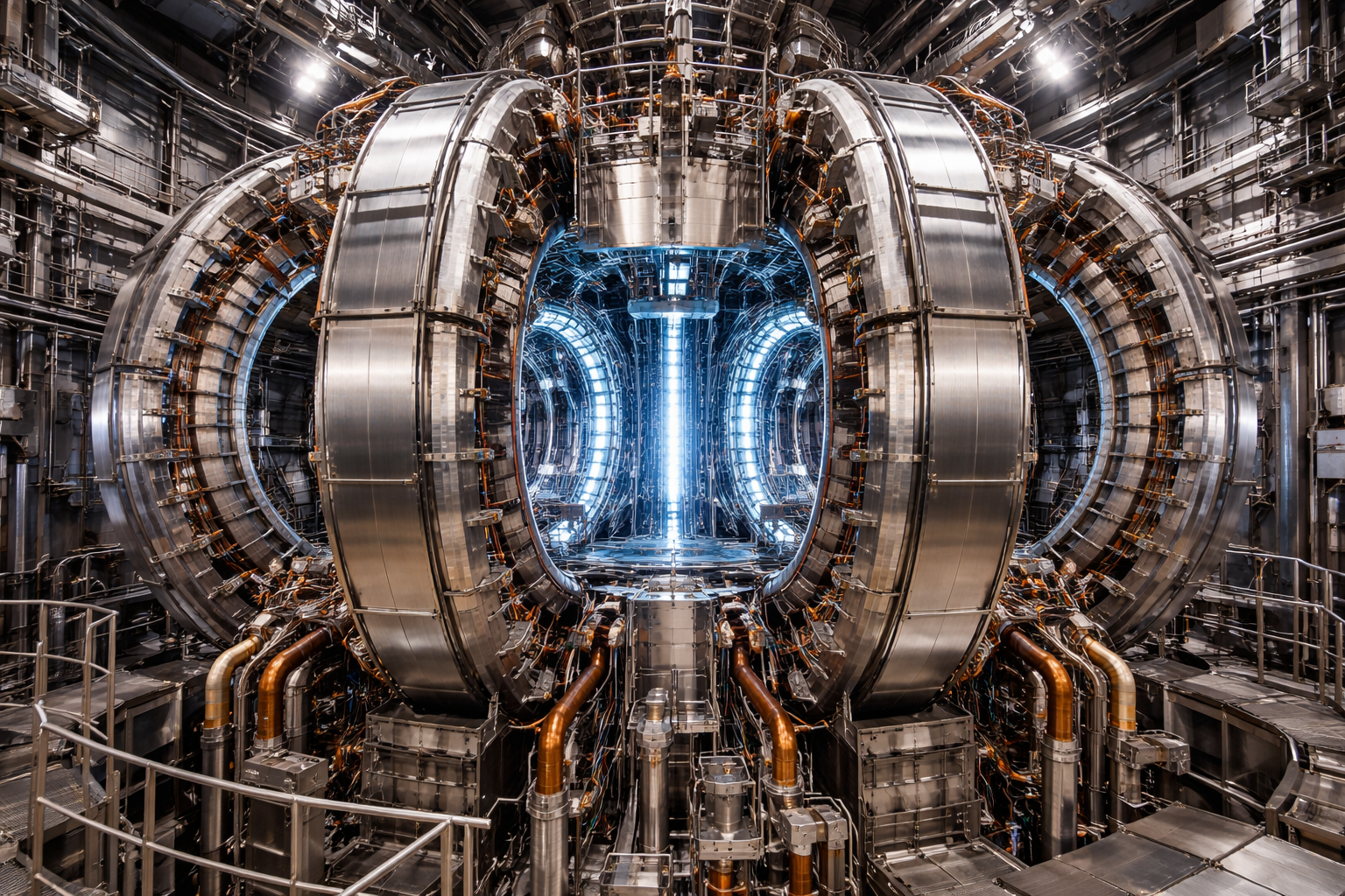
A tokamak confines plasma in a torus by combining an externally generated toroidal magnetic field with a poloidal field produced by the central solenoid, external poloidal field coils, and the plasma current itself. The result is a twisted, helical field-line topology that keeps charged particles from streaming directly into the wall. In present-day devices, the magnet system is therefore both the confinement system and the machine’s dominant structural driver. ITER’s official description is representative: its magnet system will weigh about 10,000 tonnes, store about 51 GJ of magnetic energy, and use the fields to initiate, confine, shape, and control the plasma.
II. Magnet Types in a Tokamak
The standard tokamak magnet family has four principal elements. First, toroidal field (TF) coils create the main toroidal field that provides primary confinement. Second, the central solenoid (CS) acts as the transformer primary, inducing plasma current and providing magnetic flux swing for startup and current sustainment. Third, the poloidal field (PF) coils shape, position, and vertically stabilize the plasma. Fourth, correction coils, or in-vessel control coils, compensate for assembly tolerances, suppress error fields, and help control instabilities. DOE’s tokamak overview and ITER’s magnet description both explicitly present this architecture.
Representative machines illustrate the range. ITER uses 18 TF coils, 6 PF coils, a 6-module central solenoid, and 18 correction coils. JT-60SA uses 18 TF coils, a 4-module CS, and 6 equilibrium-field coils. Smaller tokamaks can also use normal-conducting in-vessel control coils for instability control and error correction.
III. Materials and Conductor Technologies
Three broad material families are used in tokamak magnets. Older or compact pulsed machines often use copper or copper-alloy cryoresistive coils. For example, COMPASS-U uses OFHC copper / CuAg / CuZr conductors cooled to about 80 K, producing 5 T at the magnetic axis but requiring cooldown between pulses because of resistive heating.
Large superconducting tokamaks today mostly use low-temperature superconductors (LTS). ITER uses Nb3Sn for its TF and CS conductor systems and NbTi for major PF systems; JT-60SA uses NbTi for TF and equilibrium coils and Nb3Sn for the CS. These conductors are commonly built as cable-in-conduit conductors (CICC): hundreds of superconducting strands are cabled, compacted, and placed in a steel jacket, and cooled by supercritical helium.
The emerging commercial path uses high-temperature superconductors (HTS), especially REBCO tape. Commonwealth Fusion Systems states that its HTS program uses REBCO and has already demonstrated a 20 T large-bore magnet; its SPARC design targets about 12 T in the plasma core and about 20 T in the TF winding pack. HTS is attractive because a higher field allows a smaller tokamak to meet a given performance target, but it also intensifies structural and quench-protection requirements.
IV. How Tokamak Magnets Are Made
Tokamak magnets are not wound like ordinary industrial coils. ITER’s TF coils are wound in double pancakes embedded in radial plates and enclosed in large stainless-steel cases; ITER emphasizes dimensional control through winding-pack fabrication, case insertion, closure welding, and final machining because small geometry errors change the magnetic configuration.
The ITER central solenoid provides a good manufacturing example. Each module uses about 6,000 m of Nb3Sn conductor. Manufacturing includes winding, conductor splicing, reaction heat treatment, turn insulation, ground insulation, and vacuum-pressure impregnation with large resin volumes. General Atomics’ ITER CS fabrication description also shows why Nb3Sn magnets are manufacturing-intensive: the conductor is bent and joined before full structural and insulation completion, and the finished modules are enormous 110-tonne units.
JT-60SA uses a similar industrial logic: square steel-jacketed NbTi or Nb3Sn CICC, inserted into stainless-steel casings with additional cooling channels, then cold-tested at operating temperature and full current before shipment. In short, tokamak magnets are precision cryogenic structures as much as they are electromagnetic devices.
V. Size and Magnetic Flux Density
Modern tokamak magnets are among the largest and highest-energy electromagnets ever built. ITER’s TF coils are about 9 m wide by 16.5–17 m tall, weigh roughly 310–330 tonnes each, operate at 68 kA and 5 K, generate about 5.3 T around the plasma torus, and reach 11.8 T peak field on the conductor. ITER’s largest PF coil reaches 24 m in diameter and up to 6 T. The ITER CS is about 18 m tall, including structure, 4.13 m in diameter, weighs about 1,000 tonnes, and reaches a peak field of about 13–13.1 T.
JT-60SA, though smaller than ITER, is still massive: its largest magnet is about 12 m in diameter, and its TF system operates at 25.7 kA to produce 2.25 T at the toroidal axis with about 1.06 GJ stored in the TF field. By contrast, a compact cryoresistive device such as COMPASS-U produces 5 T at a major radius of only 0.894 m using copper coils, while SPARC’s HTS path aims at about 12 T in the plasma core and about 20 T on the conductor.
VI. How the Magnets Achieve Containment
Tokamak confinement depends on field topology, not just field amplitude. The TF coils create the strong toroidal component. The CS induces plasma current, which creates a poloidal field. External PF coils shape and position the plasma. The superposition of toroidal and poloidal components produces helical field lines, reducing particle drifts to the wall and enabling equilibrium control. ITER’s magnetic diagnostics material states this directly: magnetic field and flux are essential measured quantities because they define plasma equilibrium, current, shape, stored energy, and instability behavior in real time.
In practice, confinement field levels in tokamaks span a wide range. ITER’s diagnostics material places magnetic-fusion fields broadly from below 1 mT in some peripheral regions up to around 10 T in the machine, while representative machines such as JT-60SA, COMPASS-U, SPARC, and ITER occupy the roughly 2–12 T plasma-field regime and up to about 20 T on conductor for advanced HTS development.
VII. Testing, Qualification, and Magnetic Metrology
Tokamak magnets are structurally, electrically, cryogenically, and magnetically qualified. Before production, mock-up coils are often fabricated and tested to validate manufacturing routes. During production, dimensional inspection is critical because coil geometry affects field error. After fabrication, magnets are typically subjected to cold testing, high-voltage testing, superconducting transition verification, full-current or staged-current energization, and deliberate quench-protection tests. JT-60SA describes repeated low-current balancing of quench detectors, deliberate warm-up of coils to trigger quench protection, progressive current stepping, pyrobreaker testing, and cryogenic-pressure management during protection events.
Magnetic output is not measured by a single instrument. Tokamaks use Hall probes, flux loops, magnetic probes, Rogowski coils, diamagnetic loops, saddle coils, fluxgates, magnetoresistive sensors, and related diagnostics. ITER’s diagnostics notes distinguish inductive measurements of dB/dt from direct steady-field sensors, while JT-60SA and SMART describe sensor suites used for plasma current, eddy-current measurement, equilibrium reconstruction, instability detection, and stored-energy estimation. In other words, “flux output” is assessed as a full magnetic-diagnostics chain, not just a one-point Gaussmeter reading.
VIII. Operation, Maintenance, and Service Life
Superconducting tokamak magnets remain “vital” only as long as their operating envelope is maintained: temperature, current density, field, mechanical strain, insulation integrity, and cryogenic flow must remain within limits. When these limits are violated, a quench occurs, and the conductor becomes resistive. ITER explains that quenches are not rare accidents so much as expected life events of superconducting magnets; the system is therefore designed with quench detection and fast discharge to protect the coils and avoid damage. ITER also notes that more than 3,000 sensors are integrated for quench detection and that total discharge of the 41 GJ TF system takes on the order of 1.5 minutes.
Maintenance philosophy depends on machine class. In activated environments, human access becomes impossible, and remote handling is mandatory. ITER states that once nuclear operation begins, inspection, repair, and replacement in activated areas must be performed remotely. For future compact power plants using HTS, the harder problem may be service life rather than basic operation: UKAEA’s STEP publications describe short inboard magnet lifetimes where neutron shielding space is limited, while Nature’s REBCO irradiation study shows that neutron or ion damage can ultimately degrade superconducting performance, even though some partial recovery may be possible by annealing.
IX. Personnel Hazards Near Energized Tokamak Magnets
For people, the main risks are usually indirect, not “radiation-like” injury from the static field itself. ICNIRP notes that static magnetic fields do not deposit energy into tissue, but at sufficiently high levels, they can produce sensory effects, movement-related effects, implant interference, and ferromagnetic-object hazards. ICNIRP’s 2009 guidance sets a 400 mT public limit, 2 T occupational limit for head/trunk, and allows up to 8 T in controlled work settings; it also notes that much lower practical restrictions, around 0.5 mT, are used for people with implanted electronic devices and to define exclusion zones.
That means the credible on-site hazards near energized tokamak magnets are projectile risk from ferromagnetic objects, implant/device interference, vertigo or nausea in high fields, and secondary hazards during quench or fast discharge. These are standard magnet-safety issues, not unique to tokamaks, but tokamaks add huge stored energy, cryogens, large moving electromagnetic loads, and complex fault scenarios.
X. Effects on Buildings, Electrical Systems, and Equipment
For buildings, the important distinction is between the steady fringe field, remanent magnetization, and time-varying field exposure. ITER already treats nearby equipment as a serious EMC problem: equipment in port cells may see about 200 mT, while instrumentation-and-control cubicles and distribution boards in the Tokamak Building may see about 2.5–20 mT, prompting ITER to build a 275 mT static-field qualification facility for breakers, cards, valves, motors, pumps, and similar components. That is a direct indication that energized tokamak magnets can affect nearby electronics and electrical equipment if not explicitly qualified.
Structural steel is another real issue. Ferromagnetic steel can distort the field while energized and can retain remanent magnetization afterward. A recent steel-enclosure study showed experimentally and numerically that remanent magnetization in steel structures changes surrounding field distribution and can materially worsen field uniformity. NASA magnetic cleanliness guidance likewise recommends demagnetizing unavoidable ferromagnetic parts individually before assembly when a low magnetic signature matters.
For the building’s electrical and grounding system, a static field mainly biases ferromagnetic parts and sensors; the stronger coupling problem comes when the field changes during ramp-up, ramp-down, plasma transients, or quench events. Tokamak diagnostics routinely measure induced eddy currents in conductive structures, and ITER’s quench-detection documentation explicitly discusses the need to distinguish resistive voltage from inductive voltage due to field variation. So the engineering concern is not that a steady field will “electrify the ground grid,” but that a changing field can induce voltage and current in loops, trays, rebar, bonded steel, and sensitive circuits.
A nearby transformer is not usually endangered by the static field alone, as people sometimes imagine; the more plausible risks are DC bias/saturation / harmonic-noise problems if stray current paths or induced bias enter the magnetic circuit or the grounding network. Power-engineering literature on grounded transformers shows that DC magnetic bias can increase noise and harmonic content, which is a better analogy for tokamak-adjacent infrastructure than generic “EMF exposure” language.
XI. Airplanes, Wildlife, Machinery, and Electronics
For aircraft, the main plausible issue is magnetic compass deviation, not aerodynamic hazard. FAA guidance for compass calibration requires sites to be kept far from magnetic disturbances such as buildings, machinery, power lines, underground cables, pipelines, and steel mesh, and U.S. regulations require aircraft magnetic direction indicators to be installed so they are not excessively affected by magnetic fields. That means a large fusion-magnet facility near an airfield would warrant magnetic surveying if stray fields extended into aircraft-operating areas. I did not find public tokamak-specific aviation incident literature during this review.
For wildlife, the strongest plausible concern is magnetoreception. Birds and other animals use Earth’s magnetic field as a navigation cue, and recent work supports the idea that migratory birds extract positional and directional information from geomagnetic cues. However, the tokamak literature I found focuses on onsite human/equipment qualification, not offsite ecological effects. So the technically defensible statement is that wildlife effects are conceivable only if site-boundary fields materially perturb local geomagnetic conditions over biologically relevant scales; I did not find tokamak-specific public evidence that this is a common or established hazard.
Nearby machinery and electronics can be affected in more ordinary ways: ferromagnetic tools and mechanisms can acquire remanence, Hall sensors and compasses can misread, relays and magnetic pickups can drift, and electronics may require field qualification if placed in the tens-to-hundreds of millitesla range. ITER’s own qualification program is the clearest real-world evidence for that conclusion.
XII. Conclusion
Tokamak magnets are specialized, high-energy, cryogenic structural systems rather than simple electromagnets. Their essential families are TF, PF, CS, and correction/control coils; their materials span copper, NbTi, Nb3Sn, and increasingly REBCO; and their design envelope is set by magnetic field, Lorentz load, cryogenics, insulation, quench protection, dimensional control, and radiation damage. At machine scale, they routinely reach plasma fields of a few tesla, coil fields above 10 T, and now HTS development fields around 20 T. Their effects on nearby infrastructure are real but specific: equipment qualification, induced-current control, magnetic-cleanliness control, and remanence management matter much more than vague “EMF” language. For buildings and factories near these systems, the right engineering questions are field mapping, dB/dt during transients, current-return geometry, ferromagnetic substitution, remanence control, and acceptance criteria for residual field after operation.
References
[1] ITER Organization, “Magnets.”
[2] U.S. Department of Energy, “DOE Explains… Tokamaks.”
[3] US ITER, “Toroidal Field Coil Conductor” and “Central Solenoid.”
[4] JT-60SA, “Magnets,” “Coils superconducting,” “Toroidal field magnet energized,” and “Op2 Diagnostics.”
[5] ITER Organization, “Magnetic field tests help prepare for operation” and “3,000 sensors for detecting the quench.”
[6] ITER magnetic diagnostics lecture, December 2024.
[7] Commonwealth Fusion Systems, “HTS magnets” and TFMC demonstration material.
[8] ICNIRP, “Guidelines on Limits of Exposure to Static Magnetic Fields.”
[9] UKAEA STEP and related HTS-radiation work.
[10] FAA compass-calibration guidance and 14 CFR 25.1327.
[11] Steel remanence / magnetic cleanliness sources. [12] Course notes, Princeton Plasma Physics Laboratory PPPL - Present: Fusion Energy and Plasma Physics, Tokamaks, Stellarators, Plasma Particle Containment Fields
Tokamak magnet. © Copyright 2026 All Rights are reserved by ELEXANA.